Railway LUL Points
OVERVIEW
* Basic Requirements of a Point
* Interlocking Principles
* Definitions
* Circuit Definitions
* General
* Components
* Point Machines
* Supplementary Drives
BASIC REQUIREMENTS OF A POINT
* The Basic requirement of a point machine is to move and secure switchrails allowing trains to take different routes through junctions.
* The control and detection circuitry is required to ensure that the points aremoved only at the correct time, and to prove that the movement andlocking have been completed.
* When considering point control and detection, there are numerous requirements that must be satisfied .
* These are detailed below.
1. All points must be equipped with electrical detection circuits which detect that each switch rails locked or secured in the correct positions. This detection include facing point locks and ground locks where fitted.
2. The lie of the points and the position of the controlling device (i.e. the lever/system command) must be proven to be in correspondence when all movements(operation of points) are completed, i.e. in detection circuits.
3. The detection circuits must be independent of the control circuit or drive mechanism.
4. The points must be fully set to the route required (normal or reverse) and any further point movement prevented, before a train approaches the points (route holding arrangements).
5. All points which accommodate the passage of a train in facing direction must have a facing point lock which locks the switch rails in the correct position once movement of the point is complete. Air operated points which have facing passenger train movements over them must also have a groundlock. A groundlock must be detected engaged in the point detection circuits.
6. The time taken for the ‘throw’ of points from normal to reverse or vice versa should be kept as short as possible particularly in complex junction areas. Standards times between 1 and 2 seconds for electro-pneumatic points and between 3 and 5 seconds for ‘all electric points’.
INTERLOCKING PRINCIPLES
The following basic principles apply to the interlocking required for the control and detection of points:
1. All points available for use by passenger trains must be controlled directly from an appropriate interlocking systems (except spring points).
2. Points must only be free to move if they are free from all interlocking and no routes requiring the points have been set.
3. Locking must be maintained until the train crossing the points has cleared the relevant section of track.
4. All points in a signal route and overlap and those giving flank or trapping detection must be locked and proven to be in the required position in the signal control circuitry until the route and associate protection is not required them. The exception to this is under emergency operations where “remote secure” is used, only the points in the line of route need to be locked in the required position.
5. The interlocking once operated must maintain its locking until its release is requested and can be legitimately carried out. The condition for the release may be when the train has cleared the relevant section of the route or the route is free of approach locking.
DEFINITIONS
* Checklock :- A lock on interlocking (point) lever to prevent it going to fully reverse or fully normal until appropriate conditions are satisfied (E.g.lever prevented from going fully reverse until point detection shows switch rails fully reversed) (not applicable where ‘BD’ lock not provided) .
* Controlling Device :- The mechanism used by the Signalman controlling the interlocking to initiate movement of the points. This may be a lever, a switch, a button or a VDU based command.
* Correspondence :- Correspondence occurs when the detected position of the relevant point ends matches the setting of controlling device. If these do not match then points are referred as ‘out of Correspondence’.
* Detection :- The proof of the position of points (and certain locks) that is required by the interlocking.
* Detector rod :- Part of point mechanism attached to switch rail to operate detector mechanism.
* Drive Rod :- The rod connecting a point motor to the switch rails to move the points.
* Escapement :- Part of mechanism of four foot/six foot points driven by point motor and having locking dabs for facing point locks and locking ports for ground locks. The points are operated via a crank driven from the escapement.
* Facing :- A train approaching a diverging junction will be approaching a set of facing points. The train will reach the toe of the switch rail before the crossing or heel of the switch rail first and the direction of the train over these points will be in the facing direction.
* Facing Point lock :-A mechanical device to secure the switch rails in their assigned position once point movement has finished. The manner in which the locking is achieved is dependent on the type of point mechanism.
* Ground lock :-A supplementary mechanical lock to secure the switch rails in their assigned position once point movement has finished. Used to supplement the facing point lock on air operated points when disengagement of that lock due to residual air pressure or vibration could otherwise result in the unlocking of the switch.
* Interlocking:- The mechanical equipment or electrical or electronic circuitry which controls the setting and releasing of the points in a predetermined pattern, ensuring that unsafe conditions can not arise.
* Normal and Reverse :- The two possible correct position for the lie of the point ends. The primary (or straight) position is usually referred as ‘Normal’ position, whilst the secondary (or turnout) route is usually referred as ‘Reverse’ position.
* Point Machine :- Where applicable, the equipment which facilitates the powered movement (and securing) of a set of points.
* Switch Rail:- The moving section of rail on each side of a set of points.
* Stock Rail :- The fixed rail on each side of a set of points (against which the switch rail must fit).
* Trailing :- A train joining another line via a converging junction will cross a set of trailing points. The train will cross these points in trailing direction and reach the heel of the switch rail first.
CIRCUIT DEFINITIONS
* Point Circuits : – There are four elements of point circuitry used for electro- pneumatic point layouts:
– Control circuit
– Detection circuit
– Lever Lock Circuit
– Ground lock (WL) Circuit
* Control Circuits :- Points may be called to operate either by the setting of a route or individual point command from a controlling device. This circuit is means of moving the points from one position to the other i.e. normal to reverse or reverse to normal. This circuit operates the point valves ‘NW’ and ‘RW’ for air operated points.
* Detection Circuits :- This circuit provides electrical detection of the position of the facing point lock and the switch rails. Also proved in the circuit is the engaged position of ground lock, if provided.
* Lever Lock Circuit :- This is an electrical lock on the point lever which will prevent the lever or shaft from being moved whilst a train is occupying the track circuits in which the points are positioned. The lever lock circuit is selected over the front contacts of the track relay concerned.
Ground Lock (WL) Circuit
• This circuit ensures that the points cannot be moved without first proving that they are free to move. e.g. when the track locking track circuits are occupied the WL can not be energized as the feed to WL valve is fed over the front contacts of the track locking circuit.
• The WL circuit is an integral part of the points movement as it must be the first item to energies before the points try to move. This is achieved through the contacts in the point lever band ‘NC’ or ‘RC’ in case of lever operation and NLR or RLR in case of TBTC system, to move the points ‘normal’ or ‘reverse’ respectively.
• There is a ‘fail safe’ element to the WL; where by once it has been energised/lifted, the detection circuit of the points will be immediately disturbed.
• Four foot point circuits achieve this by placing a ‘back’ contact of the ‘WL’ in the ‘WKR’ circuit.
• Chair lock points achieve this mechanically; when the WL is energised it engages with the cam follower arm and places the circuit controller contacts in the mid position.
• In Clamp lock circuits the WL has to prove that it has disengaged before the point valves are allowed to operate. This is achieved through additional limit switches placed in the ground lock unit. For point drive it is always the bottom limit switch which has to be proven, the contacts of these switches are included in the ‘NW’ and ‘RW’ control paths.
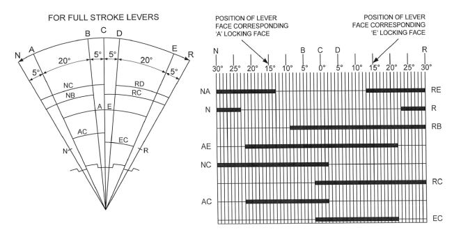
* Lever Bands :-The detection of the position of the lever in the frame is an essential requirement for the correct operation of vital circuits as in below figure. The different positions of lever bands is in correspondence with lever position.