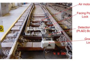
Railway Signalling SMR SMCR TSR UCR ASR ALSR UYRs OVSR OVJSLR Circuits
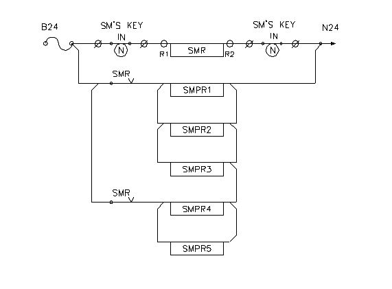
SMR/SMCR CIRCUIT
- This relay is energized when the SM’s panel key is `IN’ and turned to Normal.
- The Energisation of SMCR/SMR relay provides authorized operation of all the functions on the panel.
- When SM’s key is turned to reverse and taken out from panel by SM, prevents un-authorized operation and locks the panel in the last operated position.
Track Stick Relay (TSR) CIRCUIT
FOR SIGNALS 3,4,21 TSR IS COMBINED SINCE ALL THE THREE SIGNALS ARE CONFLICTING TO EACH OTHER

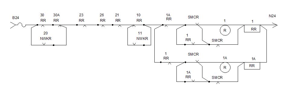
SIGNAL KNOB REVERSE RELAY(RR) CIRUIT
The switches/knobs used are 2 position type – NORMAL and REVERSE
NORMAL : Signal will be at ‘ON’ condition.
REVERSE : Knob reverse relay RR picks up provided conflicting RRs in drop. The signal will be taken off provided all other conditions are favourable.

SIGNAL KNOB REVERSE RELAY (RR)
- Bridging of SMCR front contact with respective RR front contact facilitates locking up of SM’s panel after signal is taken off and prevents rising of signal when panel is locked.
- Bridging of R band of signal switch with drop contact of SMCR prevents unauthorized normalization of signal in case SM locks up the panel.
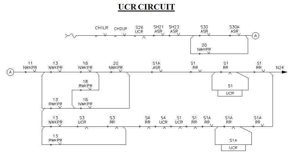
Route Checking Relay (UCR CIRCUIT)
* One signal will have one UCR. UCR will be named after the signal number.
* This relay is normally de-energized relay. It energizes when ever signal knob is reversed or signal knob reversed and route button pressed, provided all other required conditions are available.
* In UCR circuit all points in route, overlap and isolation (set& locked) ar proved.
* To achieve locking of conflicting signals, Front Contact of ASRs or back contacts of UCRs of conflicting signals are proved in UCR circuit.
* CH IN is also proved in UCR , so that once checking completed and route locked, further route should not be altered mechanically by cranking.
* UCR front contact is proved in HR circuit.
* UCR back contact is proved in ASR circuit. This is utilized to drop ASR as soon as UCR picks up i.e., to lock the Route as soon as it is checked. Back contact of UCR in ASR circuit also ensures that Signal knob is normalized before releasing the route.
ASR /ALSR CIRCUIT
- ALSR is a normally energized relay.
- Every signal will have one ALSR .
- Whenever a route is set and route-checking relay UCR is energized it causes ALSR to drop and there by locks the route.
- The drop contact of ALSR is proved in HR circuit to ensure locking of that signal route before the signal is cleared.
- ASR can be combined for the signals which are conflicting to each other
ASR/ALSR CIRCUIT CONSISTS OF 3 CIRCUITS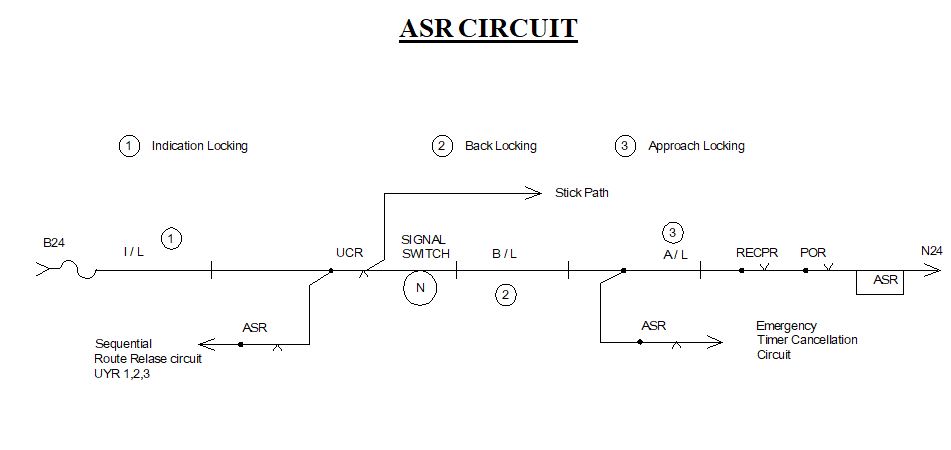
ASR/ALSR CIRCUIT CONSISTS OF 3 CIRCUITS
- Indication locking.
- Back locking.
- Approach locking
ASR gets energized through 3 ways.
(i) Only after the train travels on the entire route sequentially and clears the route.
(ii) On cancellation, with time delay when dead approach provided or approach track occupied.
(iii) On cancellation without any time delay when approach track is provided and clear.
When the train travels over the set route , ASR picks up only on the following conditions
* The train has arrived completely and cleared the entire route.
* The sequential route release relays UYR 1,2,3 have picked up indicating the sequential, directional movement and arrival of train.
* The signal is put back to `ON’ and the controlling relays & indication relays have dropped.
* The controlling switch if any, has been normalised .
* The track circuits in the entire route upto Berthing track have picked up behind the train.
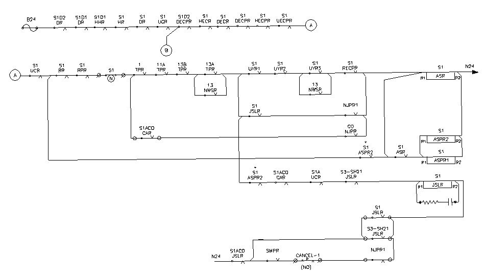
ASR CIRCUIT FOR S1
UYRs CIRCUIT

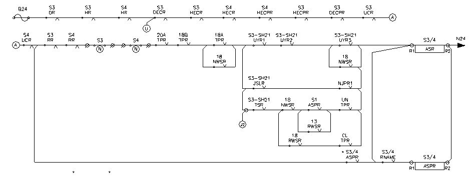
¾ ASR- COMBINED FOR S3&S4
- In this circuit, ASR is combined for signals 3&4.
- The approach path is provided for both starters.
- u for UYRs path.
- J2 for cancellation path.
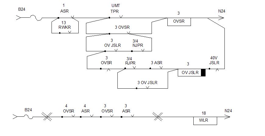
Overlap Stick Relay Circuits – OVSR & OVJSLR
* OVSR is normally energized and drops whenever the signal is taken ‘OFF’ leading towards that overlap.
* OVSR UP is proved in the WLR circuit.
Dear sir
For the overlap stick relay circuits -OVSR andOVJSLR can provide the station lay out.
Thanks
yes
Dear sir
Please can you provide the track layout of this circuitry
Thanks
yes sure