Railway Signalling Track Circuit Interrupters Presentation
Definition
* Catch points and trap points are types of turnout which act as railway safety devices.
* Catch Points
Points are provided to derail vehicles running back on rising gradients. The points may only be Unworked if traffic is in one direction only. Catch points are used to derail vehicles that are out of control on steep slopes (known as runaways).
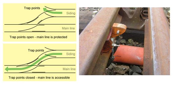
* Trap Points
Facing Points provided at an exit from a Siding or converging line to de-rail an un-authorised movement, thus protecting the adjacent Running Line. (Trap points are used to protect main railway lines from unauthorised vehicles moving onto them from sidings orbranch lines.) Either of these track arrangements may lead the vehicles into a sand drag or safety siding.)
* Catch Points
* Trap Points
Introduction (TCI)
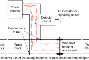
* Track circuit interrupters are used on lines which are track circuited, at trap or run-back catch points and other locations where trains may be intentionally derailed.
* The device is designed to interrupt the track circuit in the event of a vehicle leaving the track. This prevents automatic re-energisation of the track circuit after the removal of the train shunt.
APPLICATION AND CONSTRAINTS
* APPLICATION
* Track circuit interrupters are used to detect the unauthorised movement of vehicles in the following situations:
* at diverting trap points and catch points,
* at wide-to-gauge trap points and catch points (non-preferred), and
* at buffer stops or other retarding devices.
The following circuit applications are addressed:
* insulated track circuit interrupter connected in series with the track circuit, insulated track circuit interrupter feeding an independent relay, which, for a relay interlocking, is cut into the track repeat relay (TPR) circuit.
CONSTRAINTS
* Interrupter Connected in Series with Track Circuit
* Track circuit interrupters may be connected in series with the track circuit, subject to all the following conditions:
- The track circuit is of the c. type.
- The interrupter bonding carries no traction current.
- The interrupter bonding is of the opposite polarity to that of the rail on which the interrupter is situated, to prevent a wrong side failure from insulation breakdown (or contact with the rail after operation).
- The interrupter is cut into the relay end of the track circuit rather than the feed end, to prevent any residual voltage holding up the track relay if the interrupter were struck.
5. All signals reading over the track circuit concerned are, where practicable, replaced by the track circuit becoming occupied.
6. The operation of the one track circuit, where practicable, places or maintains at danger the necessary signals on all the adjacent lines.
7. Where it is not practicable to fulfill conditions e) and f), e.g. in the case of mechanically operated signals, the signals concerned shall be prevented from clearing when the track circuit associated with the interrupter is occupied.
Track circuit interrupter relay circuits
* Where a track circuit interrupter relay is used, the interrupter relay circuit shall be immune to the electrification system(s) present, generally as follows:
* In a.c. electrified areas, an external 50V d.c. supply shall be used with an a.c. immune relay, except in areas of d.c. track circuits, where a dual immune system shall be used.
* In d.c. electrified areas, a 110V a.c. circuit shall be used, with a 110/50V transrector at the relay. A separate isolated 110V supply shall be used in areas of a.c. phase sensitive track circuits.
* In dual electrified areas, a dual immune system shall be used.In addition, the track circuit at the interrupter shall be immune to the interrupter relay circuit.Further details of on-track circuits are given in Part D of RT/E/C/11600.
FUNCTIONAL REQUIREMENTS, PROVISION, CONTROL OF TRACK CIRCUITS, SIGNALLER’S DISPLAY
PROVISION
* Where trap points or catch points occur in track circuited lines, a track circuit interrupter shall be provided.
* Where necessary to provide protection from derailed vehicles, track circuit interrupters shall also be located at buffer stops. This is mandatory at friction buffer stops.
* Note that axle counters (or manual block systems) will inherently maintain the track section on the line concerned in an occupied state following a derailment. However, this will not provide protection for adjacent lines.
* Where any adjacent lines could be fouled, it may be necessary to provide a separate track circuit interrupter.
CONTROL OF TRACK CIRCUITS
When operated, a track circuit interrupter shall, in accordance with GK/RT0064:
cause the track circuit with which the interrupter is associated to indicate “occupied” (“undefined” where the interlocking permits),cause appropriate track circuit(s) on line(s) which may be fouled by derailed vehicles to indicate “occupied” (“undefined” where the interlocking permits), or otherwise place or maintain at danger protecting signals, and
* where practicable, place or maintain at danger any signals reading over the track circuit associated with the interrupter, which are not replaced by the track circuit becoming occupied (e.g. signals that are not track controlled or are not first wheel replaced).
* Where it is not practicable to fulfill conditions b) and c), e.g. in the case of mechanically operated signals, the signals concerned shall be prevented from clearing after the interrupter has been operated.
SIGNALLER’S DISPLAY
* Where practicable, operation of a track circuit interrupter shall initiate a critical alarm or separate indication on the signaller’s display.
* This is generally only practicable where the interrupter circuit is separately returned to the interlocking.
* Where all protecting signals are placed or maintained at danger by means of the interrupter operating the respective track circuit(s), it will be sufficient for those track circuits to be indicated on the signaller’s display.
GENERAL ARRANGEMENT
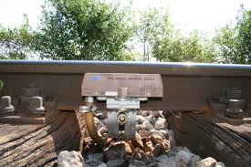
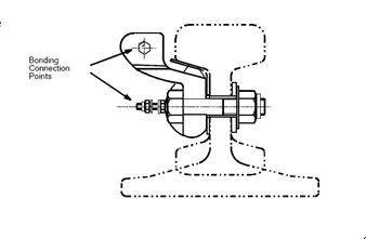
* The interrupter comprises a main body, a narrow neck and a head which is adjacent to the running edge and designed to break off when a rail vehicle passes over it. Connections are made to the head and the body such that electrical continuity is provided between them until the interrupter is broken.
* INSULATION For new work, the track circuit interrupter shall be insulated from the rail on which it is mounted.
* The arrangement is shown in Figure
MOUNTING ARRANGEMENTS
Diverting Trap Points
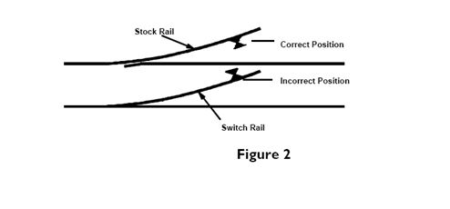
* In the case of diverting trap points and catch points, the interrupter is attached within the track circuit to the four foot side of the stock rail (as shown in Figure 2). It must not be fixed to the switch rail.
Wide-to-Gauge Trap Points (non-preferred)
* At wide-to-gauge trap points and catch points, several interrupters are required to ensure operation, as the course of a derailed vehicle is unpredictable (see Figure 3). In the case of series bonding, each interrupter shall be wired in series in the appropriate leg of the track circuit, obeying the opposite polarity rule. Otherwise, all the interrupters shall be wired in series in an interrupter relay.

Interrupters at Buffer Stops
* One interrupter is mounted on one of the running rails adjacent to the buffer stop, or other retarding device, beyond the normal stopping position. The position at friction buffer stops is detailed in Part F of RT/E/S/11752. & NR/L2/SIG/30009/E430.
Notes:
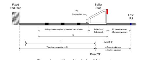
* Point ‘N’ shall be painted on the platform at a distance of at least ‘D’ from the fixed end stop. Distance ‘D’ is equivalent to the sliding distance required by the heaviest train at 5mph plus the length of the buffer stop body.
* A distance greater than ‘D’ shall be provided wherever possible to allow for higher impact speeds.
* The last IRJ shall be installed between 4m and 4.5m from point ‘N’.
* The initial position ‘I’ for the buffer beam shall be between 3.5m and 4m fromthe last IRJ.
* Initially the buffer beam must be set at point ‘I’. A track circuit interrupter (or approved detector) shall be used to detect the movement of the buffer stop before the face of the buffer stop reaches point ‘N’.
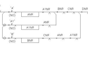
Relay Interlocking
* The interrupter relay is controlled directly by the interrupter itself and its front contacts are used to control all repeat relays of the required track circuit. Where necessary, an interrupter relay may control more than one track circuit or may be controlled by more than one interrupter.
Electronic Interlocking
* In the case of electronic interlocking, the interrupter relay generally provides an independent input to the interlocking data.
Track Circuit Assister (TCA) & Track Circuit Assister Interference Detector (TCAID) (RT/E/PS/11762)
INTRODUCTION
* Track circuits can fail wrong-side for several reasons but one of the most common is contamination of the interface between wheel and rail. This results in a relatively high resistance being presented by the train to the track circuit with the result that the track relay (or receiver) is not shunted.
* This problem became much more serious in the 1980s due to the advent of new diesel multiple units with good riding qualities. The good riding characteristics together with the small number of axles considerably increased the risk of not shunting the track circuit by reducing the scrubbing at the wheel rail interface.
Track Circuit Assister (TCA)
* To combat this effect a track circuit assister was added to the train. This device induces a high frequency (165kHz) current into the bogie axle area such that a slight rise in contamination increases the voltage between the wheel and rail and thus breaks down the contaminant. However the TCA cannot break down thicker films of rust, leaf debris or other similar contamination since the required voltage cannot be generated safely.
* Although the preferred technical name is “track circuit assister”, the device is more commonly referred to as “track circuit actuator”.
Track Circuit Assister Interference Detector (TCAID)
* To The TCAID has been developed to detect the TCA signal injected into the rails and to then provide a supplementary shunt to the track circuit and improve the probability of correct track circuit operation. A consequence is that the TCAID will only respond to TCA fitted trains.