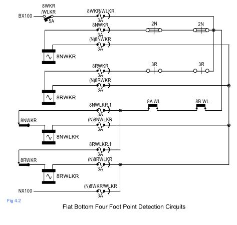
Point Control And Lever Lock Circuits
Fig 4.1 shows the Point Control and Lever Lock circuits for a set of double-ended flat bottom four foot points. The main ‘W’ fuse has been replaced by a Miniature Circuit Breaker (MCB). The 12V D.C style F3 LPR has been replaced by a 100V A.C QNHX1 plug in style ‘Q’ relay.
As this relay is AC, it is wired in parallel with the input of the lock rectifier. More recent ‘V’ style installations have been fitted with LKEs (red LED units) mounted in a panel to the rear of the frame. These LED units have an integral voltage limiting resistor and are wired in parallel with the coil of the lever lock.
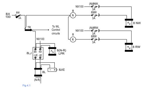
Detection Circuits
Fig 4.2 shows the Detection circuits for a set of double ended flat bottom four foot points. The design of the WL Control circuit (which we shall look at next) requires that the points (P&LD) must be detected separately from the WL. The three position WKR has been replaced by two QNHX1 line relays, which detect the points Normal (NWKR) or Reverse (RWKR).
When the points are neither Normal nor Reverse, both relays will be de-energised (equivalent to the mid position on a three position WKR) Because the polarity of the incoming feed no longer needs to be swapped over to drive the detection relays, the loops in the P&LD box have been removed and only the BX supply is switched.
Therefore only two contacts of the P&LD box are used. When the NWKR is energised and the WLs are in their ports, the NWLKR picks up. When the RWKR is energised and the WLs are in their ports, the RWLKR picks up. The NWLKR or RWLKR contacts are used in the signal selection circuitry of any signals that route a train over these points.