Railway ‘N’ Style Frame Four Foot Point Circuits
‘N’ style frames are manually operated and at the time of writing (March 2007) are still in use, mainly on the SSL lines. However these will be gradually phased out as lines are re-signalled.
In essence, the circuits used to control the points are very similar to the ‘V’ style circuits just discussed. In fact the ‘V’ style circuits were derived from the ‘N’ style ones!
The main differences are in three key areas. The first of these is the Lever Lock circuit, the second is the Point Control circuit and the third is the Point Indication circuit.
The Lever Lock Circuit
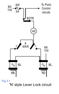
Fig 3.1 shows a Lever Lock circuit for an ‘N’ style lever frame. The main W feed fuse and the track locking are the same. There is an AE lever band in the feed to the locks. This AE band is known as the ‘anti-chatter band’.
Because the electric lever locks are fed from an AC supply they tend to ‘chatter’ and make a lot of noise. If this noise is multiplied by the number of point levers in the frame, it can amount to a considerable racket! Therefore when the lever is either fully Normal or fully Reverse the point lever lock is de-energised and remains silent.
There are two separate locks for the same lever. One will lock the lever in the NB position and the other in the RD position. This is to do with the physical layout of the locking on this type of frame.
The energisation of the individual lock is selected over a WKR contact of the position to which the lever is going. For example the NB lock is fed over a Normal WKR contact and the RB lock is fed over a Reverse WKR contact.
This arrangement ensures that the lever can only be placed fully Normal or Reverse if the points have thrown and have been detected to be in these respective positions. If the points are not detected in their corresponding position, for example when they are failing, the lever must be returned back to the original position where the points were last detected.