Railway Remote Route Secure
Railway Remote Route Secure | Remote Securing in Existing System:
1. Remote securing shall be selected to provide an alternative indication at a particular signal which is prevented from being permissive through equipment failure.
2. The indication shows that the points to be traversed on the associated route have been locked and detected in the correct position, and will be held so by route locking.
3. This indication shall be used as part of a procedure to authorise slow-speed train movement when the signal has failed to reach a permissive state.
4. Remote securing of points shall continue to function in the event of a train detection failure, wherever possible.
Operation in Existing System:
1. The Signalman provided with a push-button that operates special relays, effectively locking the points. Successful locking results in a special indication being given to the train driver.
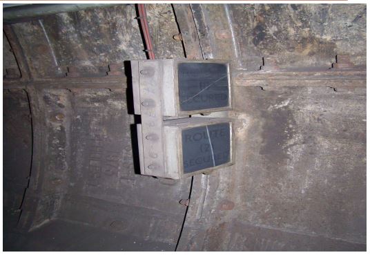
2. This takes the form of a white illuminated sign with the legend ‘Route Secure’ displayed at the signal controlling the entrance to the route.
3. The driver is instructed to pass the signal at danger and proceed at caution.
4. Where remote securing can be applied to more than one route ahead of a colour light stop signal, then more than one indicator will be provided.
ROUTE SECURE IN TBTC SYSTEM:
1. Route Secure Indications will be provided for Restricted Manual mode train moves over points and past floodgates.
2. The illuminated RS indicator will indicate to the train operator the unique path the train will follow: RS1, RS2, etc. When the RS indicator is illuminated, the point will be correctly aligned and detected (flank point detection is not required; however the VCC does reserve the flank point regardless) and will not move under or ahead of the train within the bounds of the RS move.
3. Restricted Manual trains can travel through points that are under manual control following Route Secure indications. These modes of operation would only be used in failure situations.
4. A Route Secure (RS) indicator is commanded to be lit or not lit by the SCS, after the required route has been set up.Setting of an RS at SMC or VCC
5. The RS move can be set up by a manual route reservation (MRR) or Route Secure Reservation (RSR) request to the SMC. The SMC will send the MRR/RSR request to the VCC and the VCC will reserve the tracks, points, conflict zones(CAZ), Border CAZs including an overlap for the manual train.
6. An MRR or RSR can also be command from the VCC at any time, including SMC failure.
7. When all the points have been successfully aligned, and other conditions at the site are correct, such as staff protection key switches normal or an indication from an external control systems (depots) that externally controlled points are locked and set, the command will be send from VCC to SCS to illuminate the RS indicator.
8. If RS is illuminated within a MRR or RSR for a train, the VCC will automatically cancel the RS indication when: – the front of a communicating RM train is reported to be at least 2 positions (inductive loop position) beyond the RS indicator when the move is part of an MRR; – an Non communicating train (NCT) is detected to have entered the block downstream to the RS indicator when the move is part of MRR; OR
– the train has been detected as having moved through the move when the move is part of an RSR.
Setting of an RS at LCP / DMC:
1. Upon the VCC failure, the points are required for RS route can be set individually to the correct direction by manual input of commands from the Local Control Panel (LCP) / Degraded Mode Control(DMC). It will be necessary to set each point separately by command through the LCP/DMC and then to command the RS sign to light.
2. Once the LCP or DMC command is issued to illuminate as RS sign, the SCS will evaluate that the current point settings within its area of control from a valid RS move, no staff protection key switches are set that inhibit the RS move, no opposing or conflicting RS indicators are set with in the SCS’s control area, the RS move is not blocked by a neighbouring SCS.
3. If the first criteria is not met, the SCS will reject the LCP or DMC command and operator will be notified of the rejection.
4. If the first criteria is met , the SCS will block its neighbouring SCS from setting an opposing or conflicting RS move and then the originating SCS will output the request to the SCS Relay Rack to illuminate the RS indicator.
5. If the site is under control of LCP or DMC or there are certain axle counter problems the RS moves must be manually cancelled.(from LCP, DMC, SMC or VCC as available).
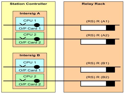
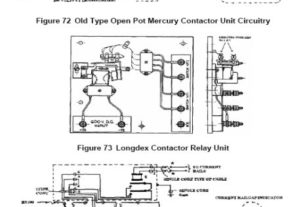
6. Slow to drop output relays keep the RS illuminated if the SCS changes over from INTERSIG A to INTERSIG B.
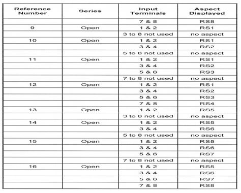
7. Because the SCS only commands ‘lit’ or ‘not lit’, the relay rack is required to select the RS aspect based on the detected position of the points in the route.
8. The points appropriate to normal signal clearance are proved in the SCS, but only those point ends which the train runs over up to the next signal (excluding non-powered trailing points) need to be set, locked and detected in the correct position before displaying the “Remote Secure” indication.
9. Once the SCS commands the RS to light, if the initial conditions (i.e. point detection) are lost the SCS does not switch off the RS. The relay rack has to do it.
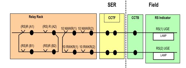
10. The SCS (either INTERSIG A or B) commands the RS to be lit, and the relay rack selects the aspect (based on 10 points normal or reverse, in this example).
Note:
1. ESP activation will not have any affect on Route Secure aspects.
2. The Track Circuit Interrupter will not have any affect on Route Secure aspects.
RS Symbol shown in SSP:
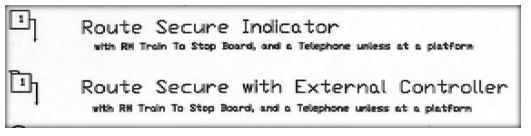
ROUTE SECURE INDICATOR UNIT

ROUTE SECURE INDICATOR UNIT, TYPES AND CONFIGURATION
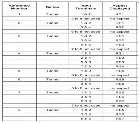
ROUTE SECURE INDICATIOR UNIT, TYPES AND CONFIGURATION