RAILWAY SURELOCK POINTS
RAILWAY CLAMPLOCK GROUND LOCK

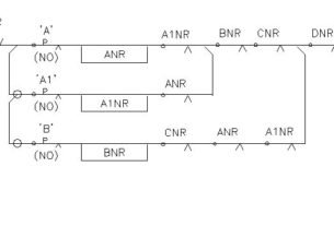
CLAMPLOCK CONTROL CIRCUITS (L.H. TURNOUT)
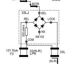
CLAMPLOCK ELECTRICAL CONNECTIONS
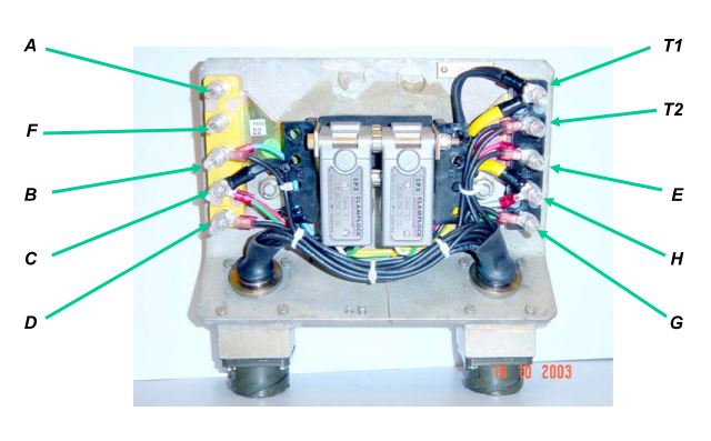
CLAMPLOCK DETECTOR ELECTRICAL CONNECTIONS
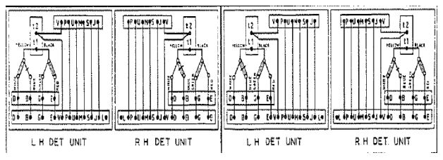
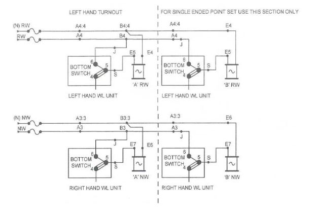
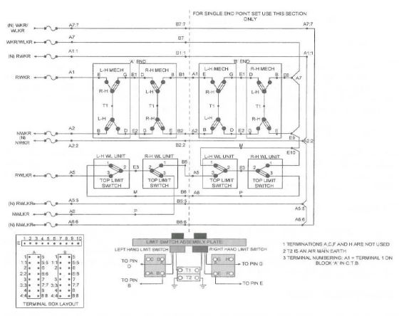
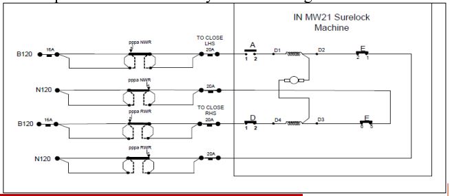
CLAMPLOCK DETECTION CIRCUIT (L.H. TURNOUT)
* Normal detection: The BX feed enters the right hand unit on terminal ‘E’, passes through the right limit switch first and then through the left switch leaving the right hand unit terminal ’D’. From here it enters the left hand unit on terminal ‘G’, passes through the right limit switch first and then the left limit switch leaving on terminal ‘B’ and then back to the NWKR to give normal detection.
* Normal WL detection: The BX feed enters the top limit switch of the left hand WL unit first and then leaves to go to the right hand WL unit top limit switch. Leaving this switch the feeds go back to pick up the NWKLR or can be used in control path of the WKR relay along with a front contact of the NWKR.
* Reverse detection: The BX feed enters the right hand unit on terminal ‘B’., passes through the left limit switch first and then through the right switch leaving the right hand unit on terminal ‘G’. From here it enters the left hand unit on terminal ‘D’, passes through the left limit switch first and then the right limit switch leaving n terminal ‘E’ and then back to the RWKR to give reverse detection.
* Reverse WL detection: The BX feed enters the top limit switch of the right hand WL unit first and then leaves to go to the left hand WL unit top limit switch. Leaving this switch the feed goes back to pick up the RWKLR or can be used in the control path of the WKR relay along with a front contact of the RWKR.
CLAMPLOCK DETECTION CIRCUIT (L.H. TURNOUT)
SURELOCK POINTS
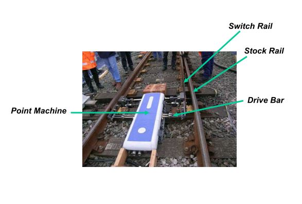
• Electric operation
• It can be mounted either between the running rails or outside the running rails
• It can be used with Bullhead, Flat bottom and asymmetric rail types
• The sure lock point drive incorporates an ergonomic, modular construction allowing high level of maintainability.
• The sure lock point drive does not require a ground lock for operation on LUL as it does not use stored energy to move
the point.
• It is provided with re-drive, so should detection be lost the point will automatically be re-driven to appropriate position.
• Each Sure lock assembly contains two 800 ohm internal heating elements which are powered from an external supply at 110V AC.
• The heaters are controlled from an internal thermostat within the sure lock, which switches them below 5 degree Celsius.
There are two basic application configuration
1. Over bearer rodding (all new point layouts)
2. In between bearer rodding (existing point layouts)
There are 3 positions in which surelock point can be installed
1. Centre i.e. 4 foot mounted
2. right hand i.e. 6 foot mounted
3. left hand i.e. 6 foot mounted
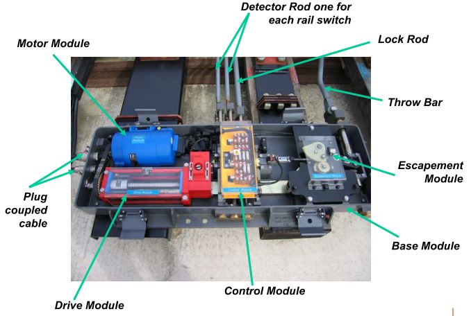
The point drive modules are Motor Module
• DC motor(split field) driving a pulley and accessible toothed belt.
• The motor is powered via 4 wire loom, 2 wires for serving the normal and reverse circuits.
• Power supply for each circuits shall be protected externally by 16A circuit breakers with in the interlocking.
• Two 15 amp cross proved cut-out switches are located on control module chassis.
• Internal control of the motor is by motor cut-off switches.
• The motor draws between 4A and 8A in normal operation, depending on the load, for average throw times of 2-3 seconds.
• Inorder to move the points, the motor is switched on by contactor relays wired to run the motor in the appropriate direction. At the same time as the motor is energised, a 7.5 second timer is started. When the required direction is made up at the end of the movement, the contactors are de-energised, switching off the motor and the timer is reset.
• If the detection does not make with in 7.5 seconds, the timer will open a back contact which will turn off the motor. This prevent extended running on the clutch, which cause damage.
Drive Module
• Clutch assembly driven pulley and ball screw.
Escapement Module
• a frame(top plate, base plate, reaction wall and side wall), roller assembly linked to drive slide bar which interfaces with base module, escapement crank and lock actuation mechanism.
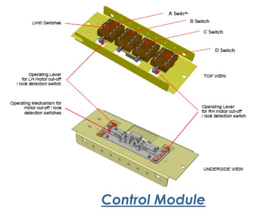
Control Module
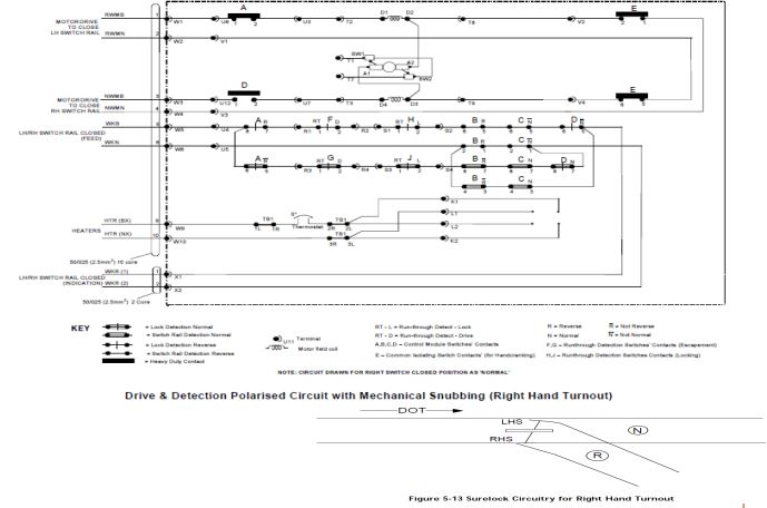
• a folded sheet metal chassis, upon mounted 4 heavy dutylimit switches for motor supply cut-off and points and lock detection.
• The 2 inner switches detect the LH or RH switch rail open and closed position.
• The 2 outer switches are incorporated in to motor control circuitry and provide isolation of motor electrical supply at the end of each point movement. In addition 2 outer switches detect the locking engagement and position of lock dog.
• Run-through detection is achieved by using two pairs of single pole limit switches, one pair incorporated into the lock assembly(part of base module) and the other pair incorporated into the escapement crank assembly (the drive arm), part of the escapement module. Both detection mechanism rely on the controlled shearing of a sacrificial link.
• Base Module :- common mounting base for all internal modules, in addition to ground connection: throw, lock and detection bars.
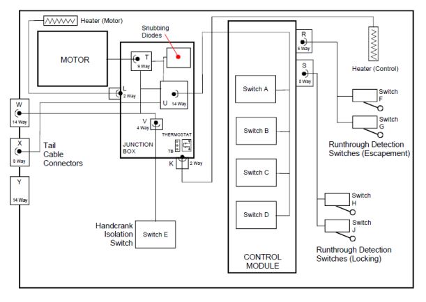
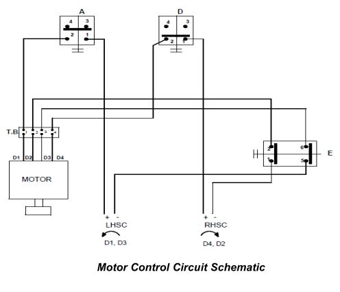
• Motor Circuitry :- There are two circuits, designated ‘normal’ and ‘reverse’ that control operation of the motor. Each circuits comprises a 15-Amp cut-out switch (switch A or D) to limit the nominal stroke of the ballscrew to 194mm and a common isolating switch (switch E) to inhibit operation when manually hand cranking.
Motor Control Circuit Schematic
Detection Circuitry
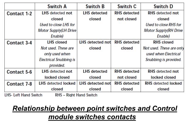
• Control module switches A and D (the outer switches). These switches detect lock engagement, and whether the lock is LHSC (Left hand Switch-rail closed) or RHSC (Right hand Switch-rail closed)
• Control module switches B and C (the inner two switches). These switches detect LH, or RH switch rail open and closed position.
• Run-through switches F and G. These are micro switches located on the underside of the Escapment Crank and provided normally closed contacts. In event of a run-through, the shear link allows a spring-loaded bobbin to move linearly, changing the state of the attached switches. Operating switches breaks the detection circuit.
SURELOCK ELECTRICAL CONNECTIONS – DETECTIONS
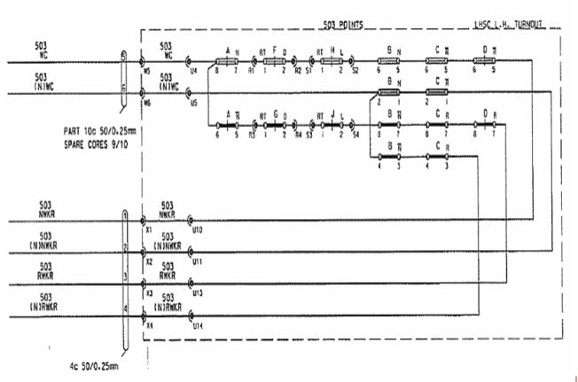
CABLE AND WIRING OF SURELOCK POINTS

CABLE AND WIRING OF SURELOCK POINTS
M-63 TYPE POINT MACHINE (1)
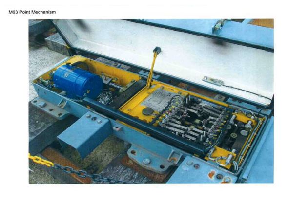
Technical Parameters
• Uses D.C. Motor with nominal supply voltage of 110V D.C.
• Nominal load Current- 3 Amp.
• Maximum constant Load Current- 7 Amp.
• Torque (Throwing force)- 1.334Nm (Nominal) to 5.338Nm (Maximum).
• Motor Inrush current – 24A for period 50ms to 100ms.
• Typical Point operating time – 4 secs.
• The point machine is normally protected by a 16 Amp fuse or a 15A miniature circuit breaker located externally to the machine in the track side control kiosk
• Cable connection Details – D.C. Motor feeds and A.C. Detection supplies are connected to the machine via 10 core cable with P14 plug coupler arrangement.
• Safety cut out- To prevent damage the point machine should not be operated for more than 7.5 seconds for which necessary protection has been taken in point control circuits.
• Slip current test – Maximum 15A
• Point Machine detection circuits are fed from 100 V A.C. Signalling supply at 125Hz at Edgware.
• The detection circuit use QNHX1relays to LUL Specification SE893 which are able to operate over the 331/3 Hz to 125Hz frequency range.
• Each point machine and each Supplementary Drive where fitted is independently detected to separate relays in the control kiosk. The wiring is designed on a 4-wire detection circuit but as the existing LUL signalling system utilizes a common Nx earthed supply so all the detection contacts are wired in the Bx leg of the circuit.
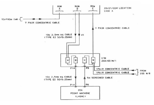
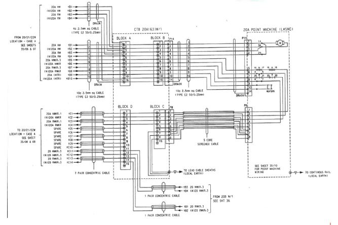
M-63 TYPE POINT MACHINE CABLE ARRANGEMENT
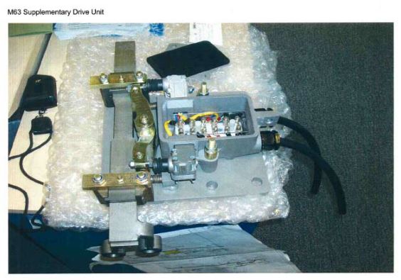
M-63 TYPE POINT MACHINE SUPPLEMENTARY DRIVE UNIT