
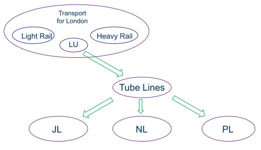
SELTRAC System Overview JNUP Thales
Jubilee & Northern Line Upgradation Project (JNUP )
SelTrac – Standard Electronic Lorenz Traffic Routing and Advanced Control
Conventional Systems of Train control
Conventional Systems and signalling are based on the fixed block principle.
Fixed Block Principles
1.The Track is divided in to section or block of fixed length
2. Under the fixed block principle to enforce minimum safe separation between the two trains, the following train must never come close to the predetermined fixed distance from the leading train. The fixed minimum number of track blocks of must always separated.
3. The fixed blocks are based on the maximum speed, maximum weight, minimum braking capability.
* To meet the current requirement the system operates under fixed block principle will require much shorter and numerous block which will result in costly wayside changes.
* SelTrac system is based on highly advanced method of achieving safe train separation under the more flexible block principle.
* The minimum safe separation between train is enforced not by fixed block of tracks by elastic block that lengthen and shorten relative to the dynamic train involves.
* As the two train head along the guide way the SelTrac system components are continuously recalculating and enforcing minimum safe distance between them which creates the moving block that separate them.
SelTrac Moving Block Configuration
Moving Block Principles
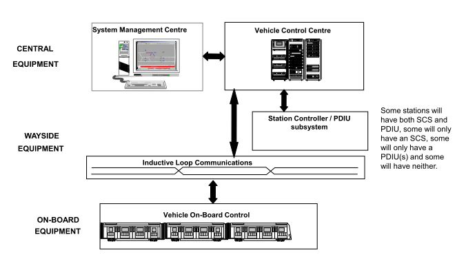
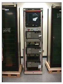
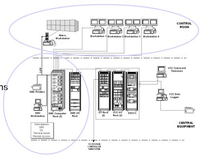
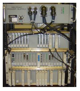
Vehicle Control Centre (VCC)
• Provides Automatic Train Protection (ATP).
• Commands vehicle operation and route setting.
• Vital Equipment / Software.Each VCC consists of 3 CPUs working in a 2 out of 3 configuration.(JL has 5 VCCs and NL has 7VCCs)
System Management Centre (SMC)
• HMI (Human Machine Interface) for command and supervision
• Automatic Train Regulation.
• Requests operational functions from VCC
• Data Logging
• Non-Vital Equipment / Software
Vehicle On-Board Controller (VOBC)
• Provides Automatic Train Protection. (ATP) and Automatic Train Operations (ATO)
• Control functions commanded by VCC
• Responsible for train movement only within speed/distance permission from VCC
• Vital Equipment / Software
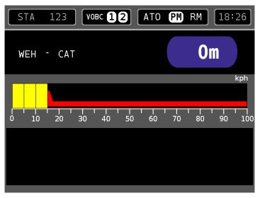
The TOD is a new display unit fitted in the cab that the Train Operator uses.
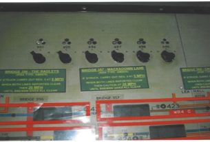
Station Controller Subsystem (SCS)
The SCS communicates with the VCC
The SCS is responsible for the safety of the system within its area of control
The SCS can perform limited interlocking functions to keep trains moving if the VCC has failedInputs to the SCS include:
• Emergency Stop Devices;
• Point Status;
• Axle Counters; and
• Peripheral Equipments.
The PDIU communicates with the VCC and the train’s VOBC via a docking loop.
The PDIU opens and closes the Platform Edge Doors as directed by the VOBC.
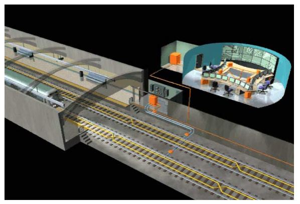
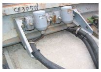
Wayside Equipment – Loops

Wayside Equipment – FIDS and EFIDS
Feed in Device (FID)
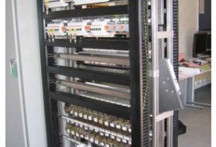
Conditions VCC to VOBC data telegrams and supervises inductive loop cable integrityLocated in signalling Equipment Rooms.
Entry Feed in Device (EFID
A standalone FID (has no external inputs or outputs) which is used to initiate communication between the VCC and the VOBC when a train enters the TBTC area.

Sections of the guideway are split into ‘blocks’. A train enters and leaves a block by passing over axle counter heads. The ‘Axle Counter Block (ACB)’ occupancy state is displayed on the SMC.
The ACBs are used for tracking trains which are not communicating with the VCC through the loops.
Track Terminology
Loops
A loop is an inductive cable, laid between the tracks, that the system uses to:
• transfer messages between the VCC and VOBC, and
• determine the position of trains on the guideway.
The maximum length of a loop is 3.2 km.
Each loop is split into ‘positions’ which the VOBC counts as it travels along the guideway. Each ‘position’ is 6.25 metres long. Each position is further split into ‘fine positions’. There are 128 ‘fine positions’ in a ‘position’.
Track Terminology
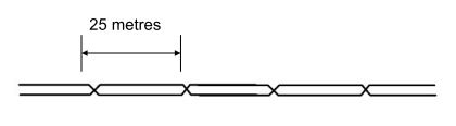
Each loop also has a ‘crossover’ every 25 meters. The VOBC detects the change in the signal from the loop at each of these ‘crossovers’ to help it determine its position within the loop. Each 25 metre section is sub divided into positions.
There are 4 positions per crossover, hence 1 position is equal to 6.25 metres. Crossovers and positions are not shown on the SMC.
TBTC Modes
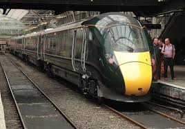
Both Passenger and Engineer trains will run on the Jubilee Line. Passenger trains are fitted with two VOBCs (1 active and 1 standby). An equipped train can operate in any one of four TBTC modes. They are:
• Automatic Mode (Auto)
• Protected Manual (PM)
• Restricted Manual (RM)
• Off Mode
Engineer Trains cannot be operated in Automatic Mode.A Train operating in Tripcock protection mode is not controlled by the TBTC system.
Automatic Mode
In Automatic Mode the train doors (and platform doors) are normally opened by the VOBC when the train arrives at a station. A switch in the cab (Automatic Door Open Override) can be selected to allow the Train Operator, and not the VOBC, to open the doors.
When the train is ready for departure, as indicated on the Train Operator Display (TOD), the train operator closes the doors and presses the ‘ATO – START’ button. The train departs the station and travels to its next stop, under the control of the VOBC.
Protected Manual Mode
In Protected Manual the train is under the control of the Train Operator, but is supervised by the ATP system. The TOD displays the maximum speed allowed and the authorised distance to travel. If the train operator exceeds the maximum speed, the TBTC system brakes the train. Door opening and closing is controlled by the Train Operator, although supervised by the VOBC.
Restricted Manual Mode
In Restricted Manual Mode the Train Operator is responsible for the control of speed, motoring, coasting and braking. A speed limit of 17 km/h is enforced by the vehicle, REGARDLESS OF LOCATION AND TRAVEL DIRECTION.
WARNING
OPERATIONS IN RESTRICTED MANUAL MODE MUST ONLY BE CARRIED OUT UNDER THE DIRECT SUPERVISION OF THE CONTROL CENTRE
Off Mode
In Off mode no train movement is allowed, the emergency brake is applied and the propulsion is disabled. The train’s position and status are still reported to the VCC.The Off mode is designed to be used in the following situations:
• When the Train Operator moves from one cab to another; and
• During overnight storage of trains
Tripcock Protection Mode
Certain areas of the guideway are still equipped with existing signalling equipment during the initial stages of the project (called migration stages) and Tripcock Protection is maintained on Transmission Based Train Control (TBTC) equipped trains during migration.
When the train is in Tripcock Protection Mode IT IS NOT UNDER THE CONTROL OF THE TBTC SYSTEM.
WARNING
OPERATIONS IN TCP MODE MUST ONLY BE CARRIED OUT UNDER THE DIRECT SUPERVISION OF THE CONTROL CENTRE
Advantages:
•Shorter Head way
•Complete speed control
•Temporary Speed restriction
•Bi-Directional operation
• Automatic schedule Regulation
• Continuous Train Identification
It’s a great easy way to learn the seltrec system which is good to understand the system.
Note: need more improvement and need to provide more documents regarding equipment like how it’s working safety life and interface with other equipment. Further need to add generation vise system documents.