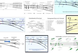
Railway Signals Use in Thales
Railway Signals Use in Thales : The signalling must provide the train operator with clear and unambiguous information about the state of the line ahead under normal operating conditions with sufficient time to react to changes of aspect.For automatically signalled areas, the red and green aspects of the stop signal will inform the train operator whether it is safe to proceed to the next stop signal or not.
Wayside signals. In LUL
User requirements
System requirements
Signalling Functional requirements:
Signals to control train movements as follows:
a) Main running lines: 2 aspect colour light system
b) For shunting movements: to, from and across main lines, mechanical or optical disc signals.
Classification of signals:
Fixed signals:
i) running signals
ii) junction indicator
Shunt signals:
i) calling on signals
ii) warning signals
Repeating signals:
i) running repeating signal
ii) fog repeating signals
iii) platform repeating signals
iv) warning lights in tunnel sidings.
Approach control signals
Draw-up signals
‘X’ signals
‘A’ signs at controlled signals
Remote securing signs.
Automatic signals shall be used on plain sections of track to keep the following trains spaced at a safe distance. These signals shall be operated purely by passage of trains. Automatic signals which protect operational flood gates shall have signal numbers prefixed by code consisting of letter F, followed by letter for the line concerned, and the letter X. Eg. FEX. Stop signals on running lines (Excluding pre-set
Shunt signal) and shunt signals shall be provided with train stop device which operates in conjunction with signal. A signal number prefixed by “X” or “FX” cannot be passed without authorisation from as operating official.
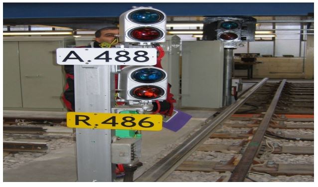
Running signals:
2 aspect colour light signals All running signals use Incandescent (luminous) lamps shall have either a double filament bulb or 2 bulbs per
aspect to enable train service to continue if one filament or bulb fails. The Second filament or bulb shall be underrun and shall act as a standby, should the other one fail. It shall be visibly obvious when one filament of the displayed aspect has failed. LED signal lamp replacements shall incorporate redundant features to achieve the above. Fibre optic or LED running signals may be considered but they shall have facilities to assist close range visibility and redundant arrangement for each aspect.
Three types of signal heads.
i) long range colour light (LRCL),
ii) Short range colour light (SRCL),
iii) Tube tunnel type.
SRCL signals shall be used for running signals on sub surface sections.
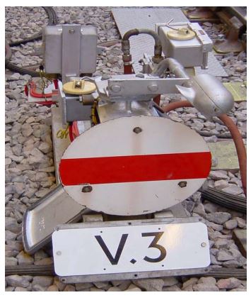
Shunt signals:
shunt signals shall be either of Mechanical disc type, with a horizontal red band on a white background, which shall be externally illuminated and cleared by the disc rotating 45 deg. In an anticlockwise manner or the fiber optic type or LED type which are self-illuminating and simulate the action of the mechanical signal by the use of an alternative horizontal or angled red bar of light on a background of white light.Shunt signal which authorize movements to two or more routes shall be provided with a route indicator.
This shall be fixed adjacent to the signal and indicates the route selected in the form of numeral which is illuminated on the display. The first route from the left is numbered “1”, the second from the left “2” and so on.Shunt signals may be situated on the same post as a running signal. In the case of fiber optic shunt signal on the same post as a running signal, the shunt signal aspect shall only be illuminated when it is required to display proceed and the stop running signal showing a danger aspect.
Electro pneumatic shunt signal have no GR. The electro-pneumatic valve that controls the supply of air to the signal is used as the GR coil and the proving contacts that confirm the signal’s position are used in place of GR contacts in the other ciruits.

Junction Indicator:
signals authorizing movements over diverging junctions shall comprise a two aspect stop signal together with one or more junction indicators.Long range junction indicators shall comprise a line of three white lights dependent on whether 1,2 or 3 diverging routes are to be indicated. For
1 route: 45 deg. from the vertical
2 routes: 45 deg. and 90 deg. from vertical
3 routes: 45 deg., 90 deg. and 135 deg. from the vertical.
For standard three lamp junction indicators, at least two lamps shall be proved alight to enable the associated green aspect to clear to proceed.
Junction indicators of reduced size shall be provided at repeating signals of diverging running signals where repeating signal can be sighted at green for the diverging route.
Reduced size junction indicators shall be provided at diverging signals in tunnels.
The Junction Indicator signals shall only illuminate if the selection for the signal is set and the train has been proved to have passed the associated sighting point.
Repeating signals (or Repeaters):
Running repeating signals shall be installed where there is a possibility of train operator not sighting a red signal in sufficient time to bring the train to rest using normal service braking at that signal. They shall display a green aspect when the repeated signal is displaying green aspect and it’s trainstop is lowered, and any track circuits between the repeater and repeated signal are unoccupied. At all other times they shall display a yellow aspect. Trainstops are not required for repeating signals.requirement of platform repeating signals shall be determined by
Some running repeating signals for the signal ahead may be situated below the preceding signal. Both aspects in the repeating signal shall be extinguished when the red aspect is illuminated in the running signal above. This shall be considered when a separate repeating signal of another signal is in close proximity to the signal. The requirement of platform repeating signals shall be determined by operational standards unit in consultation with respective service delivery unit.
Repeater signal located along with other proceeding signals
Where platform repeating signals are specified:
• The signals shall repeat the aspects displayed by station starting signals, shunt signals and junction indicators
• The “proceed at caution” aspect of shunt signal shall be repeated by a black band at 45deg. to horizontal on an illuminated white background.
• Junction indicator shall be repeated by a line of light at the appropriated angle. Fog repeaters shall be provided at a nominal 120m in the rear of the signal they repeat and be mounted at train operators eye level. They shall display a yellow aspect when the signal repeated is at danger or the tracks in between are occupied, and a green aspect when the signal repeated is clear to proceed. The yellow aspect lens shall have a black letter “F” etched into the lens. Fog repeating signals mounted on the same post as running signal are controlled similar way as repeating signals. They can be lit, usually in conditions of reduced visibility, by the operation of ‘fog switch’ at the local station. This illuminates all the fog repeaters in the local area.
• Additional signals shall be provided in tube tunnels to reduce the risk of collision during the application of the “trip and proceed rules”, where the view forward is restricted.
Speed control signals:
speed control signals shall be provided up to signals where there is insufficient overlap to permit a full speed approach. When the train occupies the timing section of the speed control signal, the red aspect shall remain on until
• A full speed overlap is available;
• The speed of the approaching train had reduced to a level appropriate to the overlap available;
• Appropriate “route-away” conditions are satisfied at the signal ahead. Signals which allow a train to draw up to the next signal shall have an extra zero(0) appended to the signal number e.g. EC21 becomes EC210. Incase of single digit numbered signals, two zeros(00) shall be appended, e.g. EC2 becomes EC200.
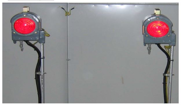
Fixed red lights
Fixed red lights shall be installed at all locations where there are no further colour light movements in that direction.Single aspect fixed red lights shall be located at the ends of sidings and terminal roads. Three fixed red lights shall be provided for each track, two side-by-side, approximately 3m beyond the normal stopping point and the other at the extreme end of the track, at sidings and terminal platforms. FRLs shall also be located at strategic locations on the running lines in order to prevent wrong road movements.
Red Flashing Light:
The RFL, activated when the out of gauge detector is operated, will act as a warning to the operator not to enter the tunnel. In the event of a flood gate being operated or loss of open detection, then the approaching signals are held at danger and additionally flashing red lights are located each side of the flood gates are illuminated.
Fixed red lights
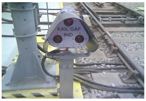
Current rail gap indicators:
Current rail gap indicators shall be used at current rail section gaps to indicate to train operators if the traction current in the next section is off. The indicators shall consist of three lamps with red lenses in a triangular arrangement in a white enameled front plate with legend RAIL GAP IND in black letters. The current rail gap repeater shall use the same signal with a yellow front plate with a legend RAIL GAP REP Rail gap indicators shall be positioned at the commencement of current rail section gap in the direction of travel. Where a route contains elements of another traction section, a current rail gap indicator shall be mounted on or adjacent to the signal and be appropriately selected for that route.
If a running signal is located less than 100m prior to a substation gap, the current rail gap indicator for that gap may be mounted on the same post, to minimize the confusion for the train operators in terms which comes first due to optical effects. A repeater need not be provided if the indicator is positioned with a station starting signal.
Where a substation gap is located between stations, a co-acting current rail gap indicator shall be provided with the starting signal at the previous station, to prevent trains setting off towards the isolated section.
Current rail gap indicators
Tripcock tester indicator:
Tripcock testers shall be sited at locations which allow for functional in service testing at least once per time tabled round trip. The exact location shall be determined by factors such as normal train movements and avoidance of installation in areas of curved track. The indicator shall be a single circular aspect which shall be illuminated as the train approaches the tripcock tester. It shall be extinguished if the tripcock is satisfactorily tested. The indicator shall be located under or near the station’s starting signal.
‘A’ sign:
A controlled signal which under certain circumstances may be treated as an automatic signal shall be provided with an illuminated ‘A’ sign. The ‘A’ sign shall be beneath the signal concerned and shall display the letter ‘A’ when illuminated and be extinguished when the signal is operating as a controlled signal. ‘A’ signs would typically be provided at sites which are normally left in through running mode, and where interlocking of the through routes is secured, for example by the use of king lever.
Tunnel siding warning lights:
In addition to other protective measures, yellow warning lights shall be installed at 15m nominal intervals in tunnel sidings where there is insufficient protection to prevent trains colliding with a fixed obstruction.
Signals not in use:
All signals not in use shall be covered to prevent the train operator from seeing them. The signal shall have it’s lamps removed and have an opaque black cover. For out door signals a white diagonal cross must be placed on the front of the signal head to indicate that the signal in not in use.
Three aspect ILM controlled signals:
Certain signals on the JL will be controlled directly from the existing IMR with an interface to the TBTC system. These signals will be capable of displaying RED, GREEN and ATC aspects and junction indicators.
The existing levers in the ILM will be retained for these signals.
Two Aspect TBTC Controlled Signals:
At certain locations, two aspect signals, capable of displaying red and ATC aspects, will be controlled directly from the TBTC system.