CAD Standards and Procedures
CAD Standards and Procedures :- References for The CAD Standards and procedures under which signalling system modifications shall be undertaken for JNUP project. (The list is not exhaustive)
1. 3CU 00550 0295 PCZZA
2. 8BH 04002 5034 URZZA
3. 8BH 04002 5033 URZZA
4. 8BH 04002 0056 UEZZA
5. LU Standard 2-01014-004 & E1122A4
6. RT/E/C/11701
Introduction
The purpose of these CAD and Procedures document is to define the method and process for the
production of Computer Aided Design and Detail (CAD) data and to maintain consistency among all drawings and data produced for Thales JNUP project.
MicroStation
All application drawings produced by Thales will be produced Using Microstation V8 2004. Signatures All signatures on “ Original” hard copy drawing to be issued shall be hand written/signed in “BLUE” ink.Deliverable Documentation Hard copies of drawings for formal submission to the client shall be in the form of copies of duly signed “Original” prints where the original drawing(s) are held at London.
Informal Submissions
Where completed drawings are submitted for advance information ahead of formal submission, they shall be fully signed copies oforiginals and rubber stamped “ADVANCE INFORMATION ONLY” or “FOR INFORMATION ONLY”. If the drawing are incomplete or unsigned, copies for issue shall be rubber stamped “UNCONTROLLED COPY”, “PRELIMINARY”, “PROVISIONAL” or “FOR INFORMATION ONLY” and supported by formal covering letter and/or transmittals. All drawing submission to the client shall be handled by the document controllers/Technical document controllers in accordance with thales document transmittal policies.
Roles and Responsibilities
Design Managers: The Design Managers (UK and canada) are responsible for independently approving any new or modified cells, mastersheets, standard circuits, border templates and drawings. Signalling Principles
Designer/Verifier:
The Signalling Principles Designer are responsible for independently checking new or modified cells, master sheets, standard circuits, border templates and drawings.
JNUP CAD Manager
The JNUP CAD Manager will check (audit) all the cells, master sheets, standard circuits, border templates and drawings for compliance, prior to their issue and use. The JNUP CAD Manager will carry out regular audits to ensure that all designs are being produced in accordance with this document.
JNUP CAD Administrators
The CAD administrator(s) will liaise with the JNUP CAD Manager on all CAD related issues. Technical Document ControllersThe Technical Document controllers are responsible for the control of all drawings between Thales and all external parties, including TLL.
Drawing Format
The standard drawing template size 420mm X 297mm as the standard printed sheet size for all internal drawings. Certain circumstances may dictate the use of a larger sheet format. On the JNUP project, TLL have provided standard A1 and A3 templates. The use of the A1 template shall be considered for use where the A3 template is unsuitable.
Border Templates
alc-sig-a3lb.dgn for A3 template – landscape border template with title block across the bottom of the sheet for bookwiring. All Volume 2 Bookwiring sheets shall use this border template for final stage (Masters). alc-sig-a3largelb.dgn for larger border – used in certain circumstances where COC is to be included in the circuits, in final stage (Recovery of COC) the border will be reverted back to standard a3lb border
A3 Bookwiring Drawings
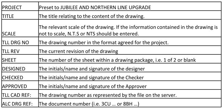
Drawing title blocks are cells that are user create seed files. All border templates are referenced into seed files and contain the following information in the title block.The data fields shall be edited with relevant details with the exception of signature & date columns which will be completed by hand in BLUE ink.
SEED FILES
A seed file comprises Border template, Border cells and all essential data settings.
SEED FILE
seed2d-a3.dgn for a3lb border template. The same seed file shall be used for A3 large lb border template.The seed files contain data fields in all locations where data is required to be entered and all the settings required to produce drawing for the JNUP project.The correct use of seed files shall be followed. The seed files and associated cells shall not be merged and/or dropped.
Drawing Fonts
The standard font for all drawings shall be the TLL corporate font “151”Arial for Microstation produced documentation including drawing templates and title blocksFor A3 Drawings, (Bookwirings) the following font sizes shall be used:
Font Height Font Width Application
1.8 1.8 General HW drawings
2.0 1.6 Superscript/subscript
2.5 2.0 General: normal font size for A3 drawings
3.5 2.8 labels and Titles
5.0 4.0 Special use
Generally for A1 drawings the following Font styles shall be used 3.5mm x 2.8mm (the font size is acceptable for use on A1 drawing that may be reduced to A3 for the purposes of issuing drawings to the client), other sizes normally accepted are 5mm x 4mm for labels and titles and maximum 7mm x 5.6mm.
Line Weight :- Line weight will be set to 0 (zero) by level in the level manager
Line Styles :- Line Styles will be set to 0 (zero) by level in the level manager
Dimension Styles:- Dimension will have all attributes set ‘by levels’
Drawing Grid System
The grid system as described below shall be applied to all drawings except those drawings that must be drawn to scale. For bookwirings, the grid system is mandatory. Grid master 2mm, grid reference 8mm to be followed.
Drawing Notes
Notes should start 2 dot spaces from the bottom and 2 dot spaces from the side. Notes will be labelled starting with 1 and going down. Settings for conventional signalling diagrams are contained in seed file seed2d_a3.dgn Master units & Sub units are mm Resolution Sub units per master unit are 1000
Circuit Diagram Drawing Production
1. Circuit diagrams shall be produced using as Master grid for placement of cells. Circuit diagrams shall be produced using an 8mm grid reference for placement of cells and “place smart line” with the “join Elements” box checked so that lines that represent wires will be a single element with as few vertices as possible.
Drawing Numbering
X001….series for index sheets
R001….series for revision history sheets
C001….series for control tables
S001….series for Signal plans
Drawing Revisions
P1, P2, P3 for informal (Preliminary) copies for information only. NOT TO BE USED FOR ANY OTHER PURPOSE. A, B, C etc. for Acceptance, Installation, Testing/commissioning and As-Built drawings.
JNUP Drawing numbering Convention
Drawing Number
ALC-J003-N391-SIG-SCH-0001
ALC-Originator
J003-Location
N391-Project reference
SIG-Discipline
SCH-Type
0001-ID
CAD File Generation
All electronically generated drawings can be manually signed by the appropriate person at each stage of the process prior to issuing the drawing. All CAD drawings will be produced using cells only. These cells will have attributes making the cells unique and will enable data extraction such as contact analysis, etc. The CAD manager will maintain the cell library.
All electronically generated drawings can be manually signed by the appropriate person at each stage of the process prior to issuing the drawing. All CAD drawings will be produced using cells only. These cells will have attributes making the cells unique and will enable data extraction such as contact analysis, etc. The CAD manager will maintain the cell library.
Should new cells be required to be added into the cell library for inclusion in any drawing, the JNUP CAD manager or
CAD administrator should be informed and only CAD manager or CAD administrator shall place the cell(s) in an approved cell library. New cells has to be checked for compliance of CAD standards and Design Manager and Principle Designer has to approve the cells. Approved cells shall be used for the production of all drawings.
Cells should not be copied, dropped, shared, nested and or modified as this will lead to failure in any automated
processes employed. Cells for conventional signalling circuits shall be 8mm from construction marker to construction marker. The snap points shall be on the grid and hence it should be minimum 8mm grid reference from snap to snap.
Standard Circuits (Generic circuits)
A Standard circuit is a complete circuit that requires no changes to it with the exception of contact and relay names. These circuits will be checked and approved by the principle designer and design Manager and then checked by the CAD manager for compliance before being placed in the “Standard Circuits”.
Exiting a Drawing after working on it or viewing
Before exiting a drawing, whether working on it or just viewing it, the file must be restored to zoom fit the screen.
To prevent Loss of work
Drawings and other documentation shall not be worked on while resident on a local hard drive, the active copy must be the copy of the server. A copy can be kept on a local hard drive as a backup only.
Good Quality Drawing
A good quality drawing is a drawing that is produced in an orderly manner. All notes line up. All balloons are in a
straight line and in numerical order. All details are in one area and in sequence, i.e. “DETAIL A”, DETAIL B” etc.
Microstation drawings
Microstation drawings are project specific and drawing templates have been supplied by the customer. The formatting
of Microstation drawings is based on customer requirements and standards.
Circuit Diagrams
On bookwiring drawings, a 2mm Grid Master, 8mm Grid Reference shall be used. This is automatically configured
using a macro that is initiated as drawings are opened.Cells will be aligned vertically and horizontally where possible and will be placed with the grid snap set to “on”.
Cell Scaling
Cells shall not be scaled but shall be placed using “Scale 1” having been created at the correct scale.
Signalling, Scale, Scheme and Bonding plans
The insertion scale of cells for use in signalling and scale plans is to be scale 1.
The Default settings for all levels is “By Level”. See tables below.
Colour shall be By Level
Line Type shall be By Level
Line Weight shall be By Level
Note: Colours listed in the tables below are Colours relating to the “Default” colour table.
Table for construction of Conventional Signalling drawings
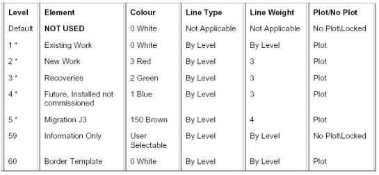
Line weight 1 should be used as above except for “Wires” on combined Red/Green drawings where line weights should be increased to weight 3 on the lines only, The Level Manager settings should not be changed. This is so that they remain clear on printed and photocopied media. Line weight 4 and above should be avoided where possible except when required.