Train Protection & Warning System (TPWS) Basic Concept:- Presentation
TPWS is a system designed to stop train:
* Passing A Signal At Danger Without Authority.
* Approaching A Signal At Danger Too Fast.
* Approaching Speed Restriction Too Fast.
* Approaching Buffer Stop Too Fast.
TPWS consists of two sensors:
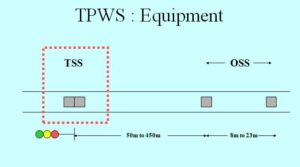
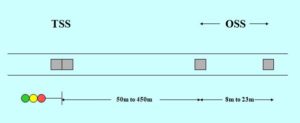
* Train Stop Sensor (TSS)
* Over Speed Sensor (OSS)
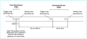
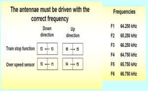
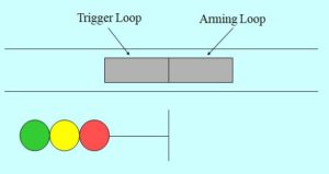
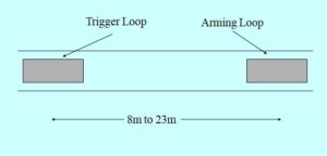
Both the OSS and TSS have two loops
* Arming loop
* Trigger loop.
TPWS will only be energised if the signal is at red.
TSS / OSS
* A Train Stop Sensor (TSS), which immediately applies the brakes of a train passing :
A SIGNAL AT DANGER
* An Over Speed Sensor (OSS), which immediately applies the brakes of a train going too fast towards :
A SIGNAL AT DANGER; A SPEED RESTRICTION; A BUFFER STOP
TPWS : Equipment
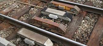
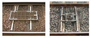
TPWS : TSS (Train Stop Sensor)
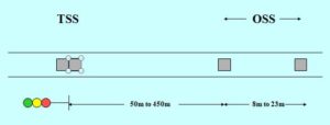
* TSS positioned at the signal post (Foot of the signal).
* Trigger Loop placed immediately after Arming Loop.
* Brakes applied on any train passing over TSS when signal at danger.
TSS – can stop a train at 40MPH within overlap
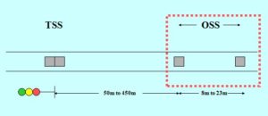
TPWS : OSS(OverSpeed Sensor)
TPWS : OSS Over Speed Sensor
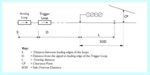
OSS loop positions based upon line speed and gradient
Timer:
- Passenger Train – 974 ms
- Freight Train – 1218 ms
If the TPWS loop is energized it emits a radio signal. When a train passes over the Arming loop this starts a timer on the train.
If the train passes over the Trigger loop with the timer still running then an emergency brake application is made.
OSS- can stop a train at 75MPH within overlap.
- TPWS LOOP
AWS & TPWS
TPWS is designed as an add-on to AWS
TPWS – Not giving any indication to the driver
TPWS – NOT Required for all main colour light signal
EXEMPTION CODES:
L- Not Protecting Passenger Line
S- Shunting Only / Not Displaying Stop Aspect
TS- Alternative Train Protection System
F- Track Layout Provides Protection
SS- Out Of Use Signal
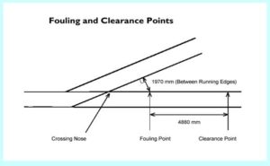
SOD – Safe Overrun Distance
RELEVANT STANDARDS
Railway Group Standard
GE/RT8030 – Requirements for a Train Protection and Warning System (TPWS)
Network Rail Company Standards
RT/E/S/10133 – TPWS Signalling Interface Design Requirements
RT/E/S/10137 -TPWS Selection of signals
RT/E/S/10138 -TPWS Transmitter Loop requirements and positioning
Clear description of signalling concepts
thanks
It would help if network rail could get their mathematical physics correct, and set the system up in a logical manner.
Happy to elaborate by private e mail.
ok
send the e mail details
Very clear and ease understanding