SMC PLC Overview JNUP
The SMC PLC system is used for the transmission of non-vital inputs and outputs between the field equipment and the SMC.
1. It relieves the SCS of having to process functions which are not safety-critical.
2. Typical functions handled by the SMC PLC are:
3. SER security and power alarms
4. PESP Override Status
5. Current online status
6. Direction indicator control
7. Platform departure indicator control
8. The PLC chosen for this application was the Mitsubishi ‘Q-Series’ PLC
9. This was chosen because of its excellent reliability and because Mitsubishi PLCs are used widely on London Underground in many applications from the JLE signalling system to the control of escalators.
Typical SMC PLC Network
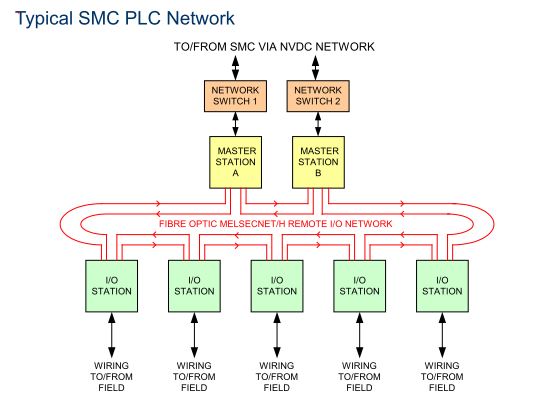
1. The SMC PLC is a distributed system comprising a redundant pair of PLC master stations communicating over a fibre ring network to remote I/O stations at each SER.
2. There will be 5 such rings for the Jubilee Line and 7 for the Northern Line, to reduce the impact of failure.
3. The fibre links are redundant, such that a single failure can be bypassed by going the other way round the ring.
4. The master stations communicate with the SMC using a standard Ethernet communication link over the NVDC network.
5. The SMC PLC does not do any logical processing of the I/O. It simply reports input states to the SMC and acts on output commands generated by the SMC. The SMC is the ‘brain’ of the system.
6. Each master and I/O station has it’s own address or ‘station number’ which is unique to the ring
Example of network failure
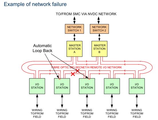
1. Diverse cables ensure one single cable failure cannot cause complete loss of communication to any station.
2. The network is routed through the SER even when it does not terminate on equipment, so that ‘re-patching’ is simple if there is a tail cable failure.
Terminology:
1. FOSE = Fibre Optic Splice Enclosure: Box where trackside fibre cables are joined together and also joined into tail cables going into
the equipment room. FOSEs are normally located at the trackside but sometimes in the SER.
2. FODF = Fibre Optic Distribution Frame: Contains the fibre transmitters and receivers for many SELTRAC equipments which communicate over fibre. For PLC, there is only a splice in the FODF, as the PLC has its own fibre transmitters and receivers. FODF is always located in an SER.
3. Network Switch = switch which handles all vital and non-vital communication traffic from the SER, including SCS to VCC, FID to VCC and SMC PLC to SMC links. These switches are located in the communications rack in the SER.
PLC NETWORK RING 1
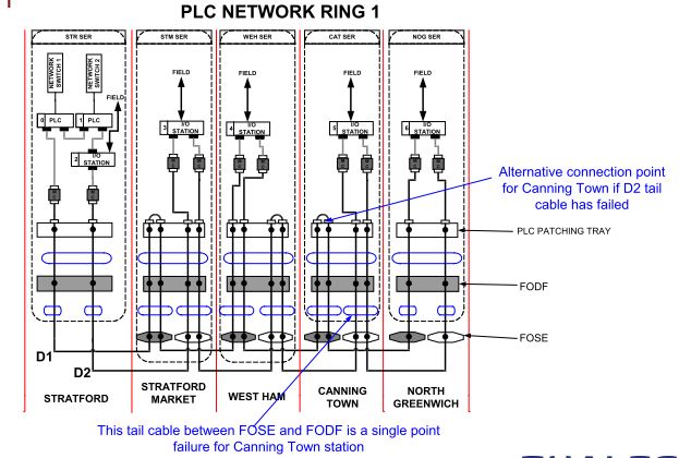
1. As well as the SMC PLC’s fibre network, we have to consider failures of the connection between the PLC
master station and the SMC.
2. The master stations communicate with the SMC over the diverse 1 and diverse 2 cables that run along the track, via the network switches.
3. The master stations can only be located at SERs where the network switches are connected to BOTH diverse 1 and 2 cables, otherwise a tail cable failure could cause the whole PLC ring to fail.
4. The JNUP trackside fibre cables contain single mode fibre cores
5. Each core is 9μm in diameter, which is so small that only one mode of propagation of the light signal can take place.

6. This type of fibre gives good quality output over long distances
7. Transmission is typically at 1300nm or 1550nm wavelength
8. Multimode fibre cores are much larger in diameter (typically 250µm)
9. They allow many more modes of propagation, which results in poorer quality output signal

10. This means that the transmission distance is much less with multimode fibre than single mode.
11. The Mitsubishi Q series PLC is designed with a multimode optical interface (typically for short range transmission in factories) operating at 850nm wavelength.
12. Therefore, the Q series is not directly compatible with the trackside fibre.
Therefore, mode converters are used between stations, as follows:
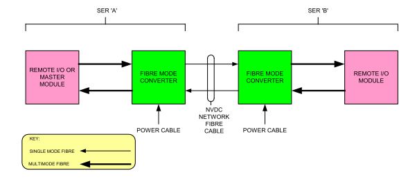
1. Each mode converter has a Tx and Rx connection for both single and multi mode fibre.
2. It converts the received multimode signal and re-transmits it as a single mode signal (and vice versa).
3. It transmits/receives at 1300nm on the single mode fibre and 850nm on the multimode fibre.
4. Each mode converter requires a 24VDC power connection (2.4W consumption typically).
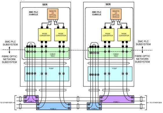
5. One pair of mode converters are housed in a 1U chassis inside the PLC cubicle.
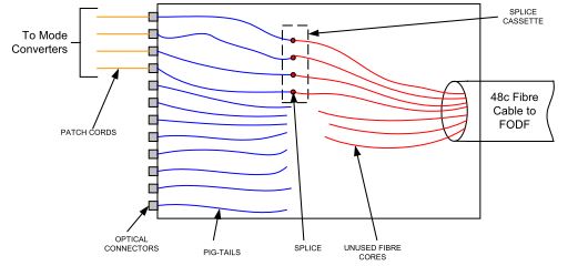
6. To permit the termination of the 48 core fibre cable from the FODF, the PLC cubicle will have a patching tray.
7. This tray comes equipped with optical connectors with short lengths (pig-tails) of fibre attached.
8. The fibre cores will be spliced into the pig-tails as required.
9. The splices are mechanically protected inside a splice cassette.
10. The tray is 1U high in the PLC cubicle.
PLC PATCHING TRAY
Detail of typical station to station fibre transmission
Each master station uses the same hardware consists of the following plug-in modules.
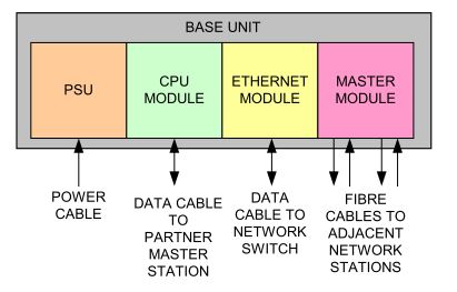
Each master station is given the station number ‘0’ for master station ‘A’ and ‘1’ for master station ‘B’.
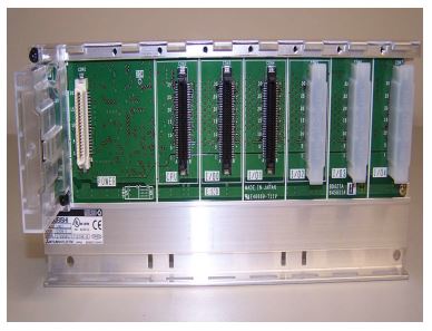
* Master station base unit contains 1 power supply slot and 6 I/O slots.
* The CPU module takes up CPU and I/O0 slots.
* The ethernet module and the master module take one slot each.
* Two slots are spare.
* Power and data transmission is carried between modules through the base.

* There are two master stations on each ring for availability.
* If one fails, the other will automatically take control within approximately 100ms.
* The synchronisation between the on-line and off-line master station is enabled by a ‘tracking’ connection between the CPU of master. station A and the CPU of master station B. This connection is made by a special Mitsubishi data cable.
* This connection makes it impossible for master station A and master station B to be in different SERs.
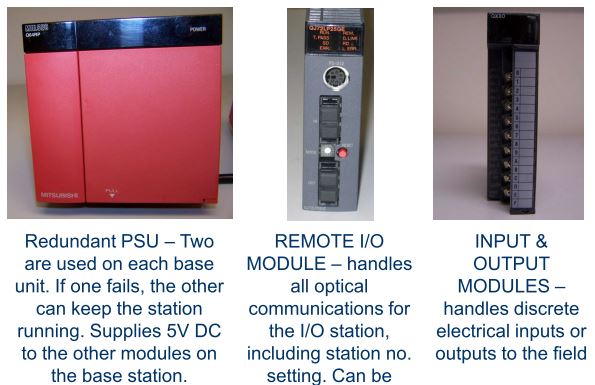
The remote I/O stations comprise of up to 8 input or output modules, redundant PSUs and optical module as follows:
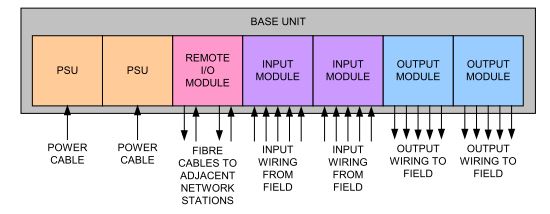
Each input or output module can connect to up to 16 inputs or outputs respectively.
* Power supply modules occupy the two left slots.
* The ‘CPU’ slot is taken by the remote I/O module.
* The remaining slots are taken by input or output modules, or are spare.
* Additional base units can be connected using the connector on the left.
* Power and data transmission is carried between modules through the base unit.
* The Mitsubishi system uses the concept of ‘I/O Numbers’ to represent locations in CPU memory where input, output or communication channel data is stored.
* I/O numbers are allocated in sequence starting from 0 on the first slot of station number 0 and increasing up to the last slot of the
highest numbered I/O station.
* Communication modules require an allocation of 32 I/O numbers.
* Input and output modules require 16 I/O numbers (one for each input or output)
* Each input or output has a unique I/O number, which represents the location in memory where its status can be found
* The I/O number definition for each SMC PLC ring can be found in the SMC PLC I/O map.
* The Q series PLC comes with thousands of functions which inform the user of faults
* Among the faults which can be detected are:
Any module failure
Any communication link failure
Any program error
* These fault reports will be used to raise alarms for the technician or operator, depending on the seriousness of the fault.
* The power supplies for the non-vital system have to be separate from the vital (relay rack) supplies to comply with LUL standards
* The SMC PLC requires:
230V AC for the master and remote station power supplies (typically 13VA each).
24V DC for the input circuits, output circuits and the mode converter power supplies (typically around 20W).
110V AC for powering trackside indicators like departure or direction indicators (typically around 80VA).
At sites with point heaters, 12V DC or 50V DC is required to drive the point heater controls (depending on the type of point heater) (typically less than 10W).
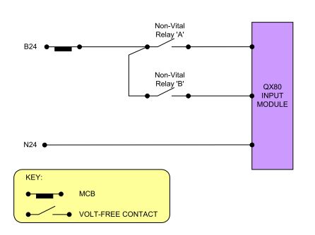
The PLC inputs, usually derived from the relay rack, will be buffered by non-vital relays.

The non-vital relays will drive the PLC inputs.

* As well as providing good electrical isolation for the PLC input module, this approach enables >10mA to be drawn over the contacts of the signalling relays (the PLC input draws <4mA).
* It also permits a standard interface where monitoring of external contacts is required (i.e. contacts in another equipment room)
* The wiring to the relay rack/CCTF from the SMC PLC cubicle will be code C15 1mm 2 equipment wire
* Connections to the input modules will use code C15 0.5mm 2 equipment wire
Typical input functions are:
* Current On Line Status
* Deadlocking Bypass Switch status
* Earth fault alarms
* Emergency stop plunger override status
* SER power alarms, fire alarm, security alarm
* Tripcock test status
SMC PLC outputs will also be buffered by non-vital relays:
The non –vital relays will switch the external loads (single cut).
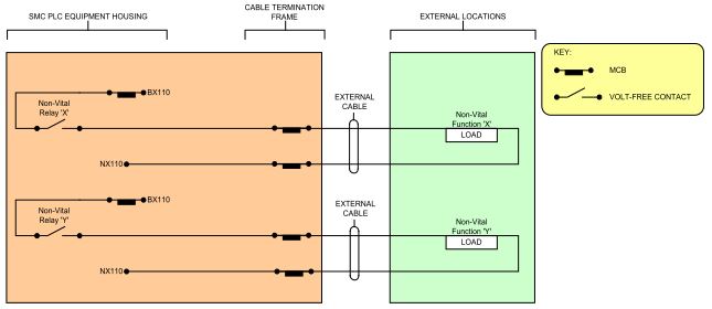
Typical output functions include:
1. Departure indicators (used to inform station staff that a train is due for departure)
2. Direction indicators (used to confirm to the train operator whether his train is routed to a passenger or non-passenger destination e.g. a depot)Special output functions are under being developed for the Mixed Mode Area and for interfaces such as Bakerloo line (Baker Street) and Stratford Market Depot.
Typical output functions include:
1. Departure indicators (used to inform station staff that a train is due for departure)
2. Direction indicators (used to confirm to the train operator whether his train is routed to a passenger or non-passenger destination e.g. a depot)Special output functions are under being developed forthe Mixed Mode Area and for interfaces such as Bakerloo line (Baker Street) and Stratford Market Depot.
* SMC PLC uses distributed architecture and optical ring network to communicate to/from field.
* PLC master stations communicate non-vital I/O to/from the SMC.
* System has a lot of built-in redundancy (but not in the actual I/O).
* Mode converters are required in the optical transmission path.
* Both inputs and outputs are buffered by non-vital relays.
SER security and power alarms, PESP Override Status, Current on line status, Direction indicator control, Platform departure indicator control, SMC PLC Overview – JNUP, Typical SMC PLC Network, Example of network failure, Terminology, PLC NETWORK RING,