RRI Free wired Route Setting
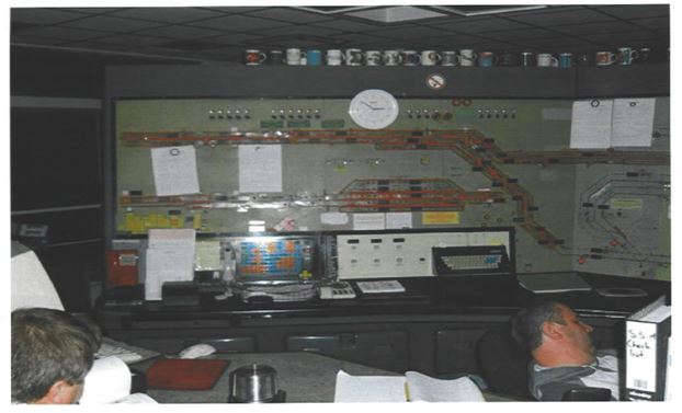
Combined Indication & control panel
Station Layout
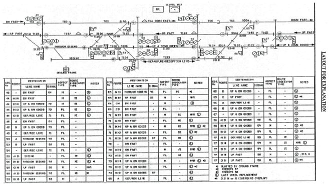
Point setting and locking sequence

RRI-Free wired Route Setting
Availability of selected route
The control table specifies the controls required for route setting Generally when the route is initiated the following checks are made to confirm that the selected route is free to be called.
Checks-
1. Points including overlap and flank points are either already set to the required position or free.
2. Directly opposing route not set.
3. Conflicting routes are not initiated.
4. Other routes of the same signal are not initiated.
5. Any other special conditions required.
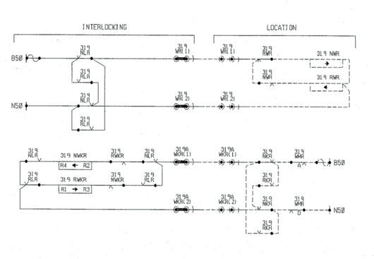
Route Lock relays
1. Each route is provided with a pair of route lock relays NLR/RLR
2. NLR is a magnetically latched relay(BR935) –
3. It is having two windings.
4. When a route is released PU winding gets to feed and the relay picks up.
5. It gets latched in even after the feed is disconnected.
6. This is the normal condition and indicates the route is free
7. When a route is initiated the other winding gets to feed and the relay gets de-latched.
8. This prevents any other conflicting or directly opposing routes are being set. RLR is a neutral relay
9. RLR is a neutral relay, normally de-energized
10. Energises when the route is set.
11. De-energises when the route is released either by normalization of route e or by TORR.
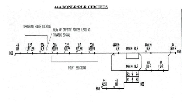
RLR/NLR circuit
1. Each circuit comprises two parts.
2. Left side of the coil called positive path.
3. Right Side of the coil called the negative path.
4. Pushbutton commands (S)R & (D)R etc. are proved on a positive path.
5. All route controls and special conditions are proved on the negative path.
Route controls are mainly three types –
Opposing Locking – opposing routes with the same setting points. Front contacts of opposing routes and front contacts of opposing USR of route section past the signal are proved.
Point Selection – all points in the route including flank points and points in overlap are either already set to the required position or free to move. other routes starting from the same signal are not locked out.
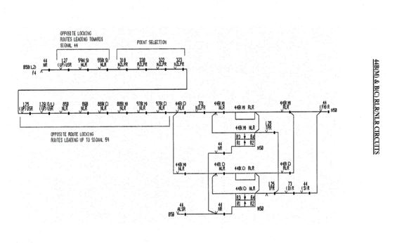
Route initiation circuit
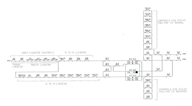
Relays in point control
| Relay | Description |
| Point NLR | Normal Point Lock Relay. Magnetically latched relay BR935. point RLR to be de-latched first for latching NLR. When latched calls the point for Normal operation. |
| Point RLR | Reverse Point Lock Relay. Magnetically latched relay BR935. point NLR to be de-latched first for latching RLR. When latched calls the point for Reverse operation. |
| WZR ↓ | Points free relay. Slow to release relay BR934. Must be energized to unlatch point NLR and point RLR. De-energized whenever the points are called by route or individual point relay. |
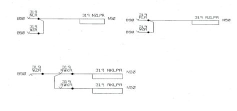
| NKLPR | Points set, Locked and detected Normal |
| RKLPR | Points set, Locked and detected Reverse |
| NZLPR | Points set Normal or free to be set. |
| RZLPR | Points set Reverse or free to be set. |
| NWKR | Points set and detected Normal. |
| RWKR | Points set and detected Reverse. |
Point status
Points normal or free
Points reverse or free
Points normal and locked
Points reverse and locked
Points called to the required position
Point control and detection circuits

I am a signalling system engineer currently worked on a company and mainly we are doing basically EI Installation in Indian Railway. I want to get connect with you.
ok thanks