Railway Single Section Digital Axle Counter
Eldyne Single Section Digital Axle Counter
1.1 Introduction
The AzLS system consists of at least two detection points Zp30CA-2, one at each end (entry & exit) of the track section to be monitored. It consists of following parts:
(a) Outdoor Trackside system consisting of
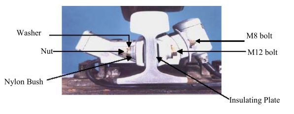
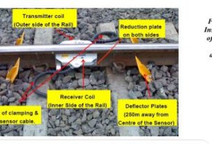
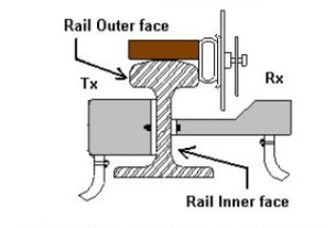
(i) Rail contacts (SK30H) – It consists of two coil sets Sk1 and Sk2, both installed on the same rail. The transmitter heads (Tx) are installed on the outside of the rail and receiver heads (Rx) are installed on the inside of the rail directly opposite the respective Tx heads. The two Tx coils are fed with different frequencies (approx. 30.6 kHz and 28 kHz). The SK30H is fitted by three bolts to the web of the rail. The vertical position of the respective mounting holes depends on the rail profile.
(ii) Track-Side Electronic Unit (EAK). SK30H and EAK together form one detection point Zp30CA-2. Each Tx/Rx head is equipped with fixed cables for connection to the electronic junction box (EAK30H). (available in lengths 4m, 5.5m and 8m)
(b) Communication Link (A pair of star quad cable)
(c) Reset Relay (1000 ohm AC immunized Q series)
(d) Vital Relay (1000 Ohm AC immunized Q series 24 V 8F/8B)
1.2 Fixing of track devices after replacement of rail Drill the mounting holes on the rail web in correct position as per following approximation formula: a = (0.409 * h), where a = height of the mounting hole, h = height of the rail
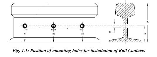
a1 or a2 or a3 = a calculated +1.5 mm
b =13 mm + 0.2 mm
c =148 mm + 0.2 mm
Maintenance of AzLS Eldyne SSDAC
Height of mounting hole for different rail profiles is given below:
Rail Profile — 90 lbs — 52 Kg — 60 Kg
a [mm] — 56 mm — 63 mm — 68 mm
The final three holes of diameter 13mm are drilled on the rail web with the help of drilling jig. consisting of:
(i) Drilling template
(ii) Mounting device for the drilling machine
(iii)Templates for the standard rail profiles
(iv) Fastening device
(v) The drilling machine
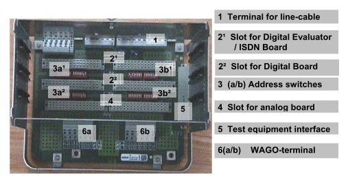
Termination details of EAK
The connections for Power Supply, Communication and Vital relay in the EAK are as under:
A shorting link is to be provided between
44 & 38 – if the evaluator card is used in middle slot.
41 & 35 – if the evaluator card is used in outer slot.
Data link 1 for Outer Slot (for connection to other end DP of AzLS) – 5
Data link 2 for Outer Slot (for connection to other end DP of AzLS) – 21
Data link 1 for Inner Slot (for connection to other end DP of AzLM) – 6
Data link 2 for Inner Slot (for connection to other end DP of AzLM) – 22
Power Supply (24 V+) – 2
Power Supply (24 V-) – 18
Relay Supply (24 V+ through a 500mA fast blow fuse for Evaluator card at outer slot) – 39
Relay Supply (24 V- for Evaluator card at outer slot) – 33
Relay Coil ( For Evaluator card at outer slot) – 40
Relay Coil ( For Evaluator card at outer slot) – 34
Relay Supply (24 V+ through a 500mA fast blow fuse for Evaluator card at middle slot) – 42
Relay Supply (24 V- for Evaluator card at middle slot) – 36
Relay Coil ( For Evaluator card at middle slot) – 43
Relay Coil ( For Evaluator card at middle slot) – 37
A shorting link is to be provided between
44 & 38 – if the evaluator card is used in middle slot.
41 & 35 – if the evaluator card is used in outer slot.
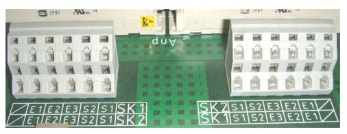
The connection of integral cables of rail contacts in EAK are as below:
Rail contact and wire colour Terminal on Zp30CA-2(AzLS)
Rx 1(black) – Sk1 / E1
Rx 1 (transparent) – Sk1 / E2
Rx 1 (blue) – Sk1 / E3
Tx 1 (transparent) – Sk1 / S2
Tx 1 (black) – Sk1 / S1
Tx 2 (black) – Sk2 / S1
Tx 2 (transparent) – Sk2 / S2
Rx 2 (blue) – Sk2 / E3
Rx 2 (transparent) – Sk2 / E2
Rx 2 (black) – Sk2 / E1
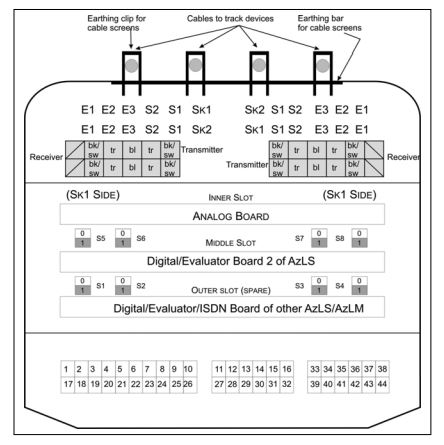
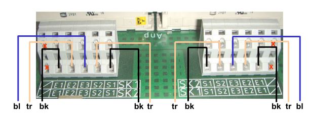
bl – Blue bk – Black tr – Transparent
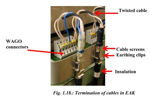
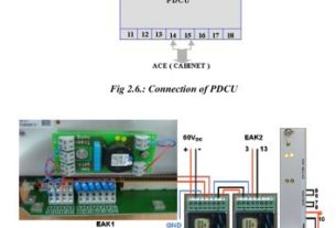
(b): Actual view of terminals on backplane of EAK
Adjustment of Rail contact Tx head with Dummy wheel and Tool Kit
The Tx head is adjusted such that the received rectified voltage produced when a wheel is present has the same amplitude but the opposite polarity as the voltage produced with the
wheel absent.
1. A dummy wheel is required for the adjustment of the rail contact.
2. On main lines the dummy wheel is normally set to 40mm.
3. During adjustments the dummy wheel must be kept vertically at the centre of Rx heads.(Fig.).
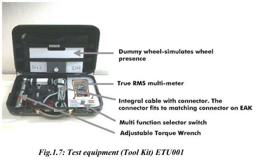
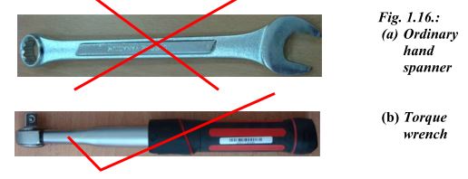
For adjustments, Tool Kit ETU001 has to be used only with its dummy wheel, true RMS multimeter and adjustable torque wrench (Fig.1.6 & 1.7).
Test equipment (Tool Kit) ETU001
Test equipment ETU001 is utilized for
1) Signal voltage level and frequency measurement.
2) AC & DC Current /Voltage measurement. During Installation, Testing, Commissioning, Diagnosing and Calibrating the Outdoor Unit of AzLS & AzLM Axle Counters.
Contents of Test Equipment
1) True RMS digital multimeter with probe set (Type Fluke-177)– 1 no.
2) Extended wired Socket to interface with diagnostic plug – 1 no.
3) Selector Switch on panel-base – 1 no.
4) Adjustable reversible torque wrench (Type Norbar –6013011)- 1 no.
5) Deep Socket inserts with (13 mm & 19 mm) – I set.
6) 19 mm combined double ended spanner – 1 no.
7) Dummy wheel – 1 no.
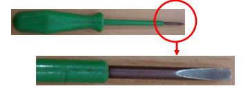
8) Screw driver individual (Type Wago-210119) – 1 no.
9) Screw driver set (Type Taparia 812) – 1 set.
10) Screw driver individual (Taparia-932) – 1 no.
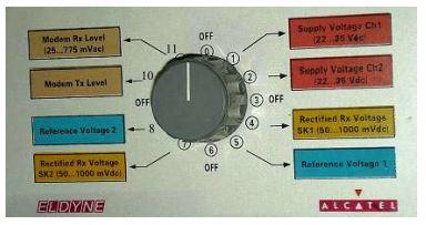
Functions of Selector Switch in ETU 001
1. Selector switch position 1: Shows the value of the output of 1st internal DC-DC Converter (Channel1) in Analog card.
2. The selector switch position 2: Shows the value of output voltage of 2nd internal DC-DC Converter (Channel2) in Analog card.
3. Selector switch position 3: OFF
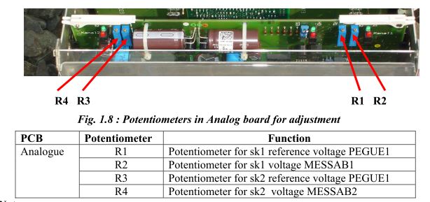
4. Selector switch position 4: Shows the rectified Rx voltage (MESSAB1) for SK1. For fine adjustment the potentiometer R2 on the Analog board of EAK should be used.
CAMTECH/S/PROJ/12-13/HB-DAC (M)
Section I – Maintenance of AzLS Eldyne SSDAC
1. Selector switch position 5: Shows the value of reference voltage for SK1 (PEGUE1). This can be adjusted by the potentiometer R1 on the Analog board.
2. Selector switch position 6: OFF
3. Selector switch position 7: Shows the rectified Rx voltage (MESSAB2) for SK2. For fine adjustment the potentiometer R4 on the Analog board should be used.
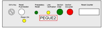
4. Selector switch position 8: Shows the reference voltage for SK2 (PEGUE2). This can be adjusted by the potentiometer R3 on the Analog board.
3. Selector switch position 9: OFF
1. Rotate R2 (or R4) clockwise to increase the Rectified Voltage MESSAB1 or MESSAB2.
2. Rotate R2 (or R4) anti-clockwise to decrease the Rectified Voltage MESSAB1 or MESSAB2.
3. Rotate R1 (or R3) clockwise to increase the Reference Voltage PEGUE1 or PEGUE2.
4. Rotate R1 (or R3) anti-clockwise to decrease the Reference Voltage PEGUE1 or PEGUE2.
Switches
Switch – Function
S1 , S2 – Switch fixed by factory in position 1.May be put into position 2 for using rail contact with longer cable length.
S3 – Switch fixed by factory in position 1.May be put into position 2 to raise the transmitter power of the rail contact for better signal to noise ratio.
Parameters to be checked for adjustment of rail contact
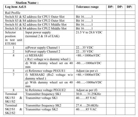
a) Output of 1st internal DC-DC Converter (Channel 1): Specified range 22VDC to 35VDC.
b) Output of 2nd internal DC-DC Converter (Channel 2): Specified range 22VDC to 35VDC.
c) Rx voltage (MESSAB1) for SK1: This should be positive without dummy wheel. After placing the dummy wheel on Rx1 vertically on the center, the MESSAB1 voltage should be negative. In ideal condition and for proper adjustment of rail contact, MESSAB1 voltage without dummy wheel should be equal to the MESSAB1 voltage with dummy wheel but having an opposite polarity. The value of MESSAB1 should be within 80mV to 1000mV depending upon the drill position and rail profile.
d) Rx voltage (MESSAB2) for SK2: Same as that for Rx voltage (MESSAB1) for SK1.
e) Reference voltage for SK1 (PEGUE1): This is made equal (or ±2%) to the value of MESSAB1 as measured without the dummy wheel.
f) Reference voltage for SK2 (PEGUE2): Same as that for Reference voltage for SK1 (PEGUE1).
Voltage & Frequency of Tx heads
The voltage and frequency of the transmitter heads are to be measured by true RMS Multimeter only. For this purpose additional probe set is provided with ETU001. These readings can be taken at connector terminals S1 & S2 of both Sk1 & Sk2 inside EAK.
of voltage and frequency
Checking of Power supply voltage to EAK
Recommended power supply for EAK is 21.5 V DC to 28.8 V DC (for 24V version) and 54 – 120VDC (for 60 – 120V version). Measure the power supply voltage fed to the track side electronic unit with the meter and the probe set directly to the power supply connector terminals 2 (+) & 18 (-).
Communication (data) between two EAK
1. Communication pair is connected to
2. Connector 5 and 21, if Digital Card is installed in outer slot
3. Connector 6 and 22, if Digital Card is installed in middle slot.
Vital Relay output
If Digital Card is installed in outer slot
Check at Connector 33 and 39, for on-board vital relay input
Check at Connector 34 and 40, for on-board vital relay output
If Digital Card is installed in middle slot
Check at Connector 36 and 42, for on-board vital relay input
Check at Connector 37 and 43, for on-board vital relay output
Voltage at relay should be more than 20 V.
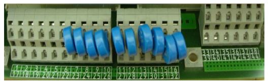
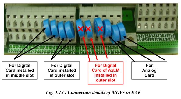
MOVs – AzLS
Adjustment procedure
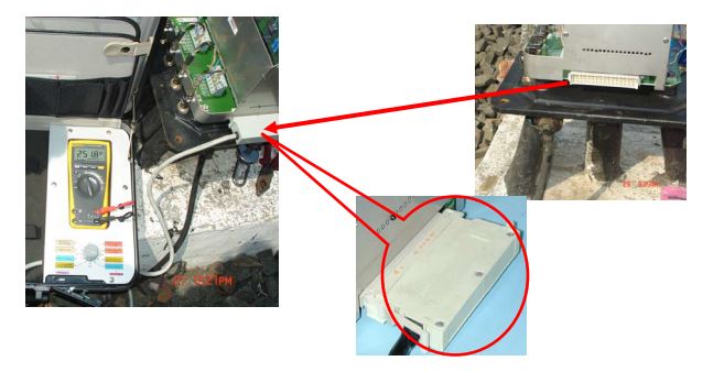
Connect the test equipment to the diagnostic port of EAK as shown in fig.1.13
Steps to adjust the rectified voltage MESSAB1
1. Put Selector Switch to position 4.
2. Measure the rectified voltage with and without dummy wheel.
3. Turn Potentiometer R2 on the Analog board to positive max.
4. The rectified voltage without dummy wheel must be set to positive maximum.
5. If there is a big difference between the positive value and the negative value, move the Tx heads upward or downward along the serration and adjust to optimum position. Taking the transmitter head upwards increases the negative voltage and decreases the positive voltage and vice versa.
6. Adjust using Pot. R2 such that rectified voltage with and without dummy wheel are absolute equal (equal but having opposite polarity). Tolerance <=30mV.
7. After getting the positive and negative voltages within the above specified tolerance limit tighten the transmitter head properly with the torque wrench set at 25 Nm.
Trolley suppression
For Trolley suppression to be effective, the positive voltage (without dummy wheel) should be greater than the negative voltage (with dummy wheel) by a value not less than 30 mV so that the rectified Rx voltage does not go to negative with the specified trolley wheel. It is recommended that the adjustment should be done using a spoke trolley wheel that is normally used in the section.
MESSAB2
Repeat the above procedure for MESSAB2 (using Selector Switch position 7, and Potentiometer R4 on the Analog board).
PEGUE1
1. Put Selector Switch to position 5
2. Measure voltage
3. Adjust using potentiometer R1 on analog board such that PEGUE1 = MESSAB1(without dummy wheel) Tolerance +-2%
PEGUE2
1. Repeat for PEGUE2 using Selector Switch position 8 and potentiometer R3 such that PEGUE2 = MESSAB2 (without dummy wheel) Tolerance +-2%.
1.9 Reset Box
ERBS-02 is the reset box for Alcatel’s Single/Double Section Digital Axle Counter ZP30CA-2 (AzLS). This provides the basic resetting pulse (24VDC) for reset relay, which is used for a polarity reversal of power supply to the EAK (the track side electronic unit) for
approximately 3 seconds. The front panel of the terminal consists of:
1. Reset Key
2. Push Switch
3. Reset Counter
4. Power ON indication – YELLOW LED
5. Preparatory Reset indication – GREEN LED
6. Line Verification Indication – YELLOW LED
7. Section Clear / Unoccupied indication – GREEN LED
8. Section Closed / Occupied indication – RED LED
Additionally a buzzer is provided to give audio indication that the 3 second reset pulse is on.
Steps to initiate a reset
1. Insert the KEY, turn it clockwise and then push. Simultaneously, insert and turn the Cooperative SM’s key if provided. (H & R are to be shorted at selection jumper J1 on PCB if the Cooperation / Line verification is required otherwise P & R are to be shorted).
2. While KEY is in turned position press the Reset Push Button for a specific section momentarily.
3. BUZZER sounds for 3 seconds and then stops.
4. Turn back the KEY anti-clockwise and take out.
Each reset is registered in the sealed reset COUNTER unit. The count increases by one after each reset commanded by the operator.
Types of resetting for AzLS
AzLS V1.1 provides four types of reset:
1. Single point preparatory reset (for berthing section)
This reset does not clear the section immediately. It is sufficient that one of the detection points of the relevant section receives a preparatory reset. After carrying out the preparatory reset, a train must pass through the section on “caution running conditions”. Only then the section will be cleared.
2. Two point co-operative preparatory reset (for block section)
The reset command is to be applied to both detection points within one hour. If this time elapses, the reset command is rejected. The other conditions are same as given in clause 1 above.
3. Single point hard reset (for point zone)
It is sufficient that one of the detection points of the relevant section receives a hard reset. In addition to this pressing and turning of verification switch is required. The hard reset clears the section immediately.
4. Two point Co-operative hard reset
The two point hard reset is initiated through individual external relay circuits which reverse the polarities of the supply voltages to at least two detection points of the section.
Check points for maintenance
1. Carry out visual inspection of trackside equipment i.e. EAK, rail contacts and integral cables (connecting leads), earthing etc.
2. Check physically whether the rail contacts and cabling including earthing connections are proper.
3. Ensure that Tx heads are clear of rail.
4. Ensure the proper size and tightness of deflectors and that these are fitted at least 250 mm away from rail contacts (Tx/Rx coils).
for proper fixing of Track side connection box (EAK) on the mushroom base plate and all 4 nos. screws are tight.
5. Ensure that cable armours are properly earthed in location box.
6. Check for proper spacing (min. 350 mm) and packing of sleepers on which track devices are fitted.
7. Check that the earthing connection of mushroom cover/apparatus case is intact and in good condition, the earth lead wire and nut connecting earth wire etc. are not corroded.
8. Check that cable pairs used are properly dressed and terminated in such a way that no conductors remain exposed and check that no individual conductor are made spiral. These should be twisted in pair to improve EMC.
9. Check that mushroom cover is properly fixed and there should be no possibility for entry of rain water.
10. Check the input voltage at location box/EAK keeping the charger OFF for at least 15 min. Voltage at location box/EAK should not go below 21.5 V for 24 V EAK and 54 V for 60 V EAK.
11. Check ripple voltage of power supply at EAK, it should not exceed 10 mv peak to peak.
12. Check rectified voltage (with dummy wheel) and reference voltages are within limit.
13. Check the cards are in proper position and both analog and digital cards are fitted firmly in their corresponding slot.
14. Measure the earth resistance and paint its value on earth enclosures/nearest wall. If required take suitable steps to improve the earth resistance. It should be less than 1 Ohm.
Do’s & Don’ts
1. For reduction in temperature, paint the inside and outside of mushroom cover (apparatus case for EAK) with temperature retardant paint (white).
Note: The newly fabricated mushroom covers are supplied with a coating of paint on inside and outside faces by the manufacturer hence painting is not required.
2. Always use 13mm high speed drill bit to drill holes on rail web.
3. Place foam packings between top of the Digital/Analog cards and dust cover to avoid loosening due to vibrations. (As per practice in BPL division W.C.Rly.)
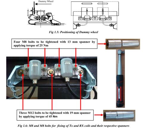
4. Tighten M8 bolts (on transmitter heads) with torque of 25Nm and M12 bolts (to fix rail contact on rail web) with torque of 45Nm. Torque greater than specified value will break the bolts and torque less than specified value will make the rail contact loosely fitted.
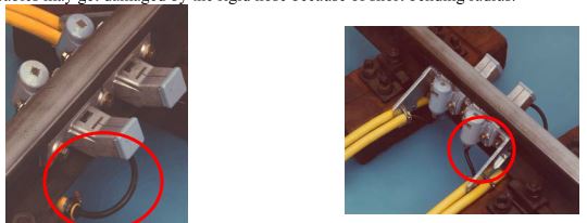
5. The rail contact integral cables must be free to loop near the Tx-Rx heads. Therefore the protective hose must not be fitted up to the rail contact. Otherwise the rail contact integral cables may get damaged by the rigid hose because of short bending radius.
6. Never use any kind of hand spanner to fix the rail contact bolts. Use only torque wrench.
7. To set the addresses of detection point computers, use ball-point pen – never use pencil.
8. During adjustment of MESSAB voltage set the corresponding potentiometers at positive maximum. After that try to avoid using the potentiometer – adjust voltage by repositioning the Tx heads.
9. Never set the addresses while the detection point is live.
10. Never plug in or pull out the analog card and digital/ISDN (evaluator) card while the
detection point is live.
11. Avoid any kind of loops in the rail contact cables.
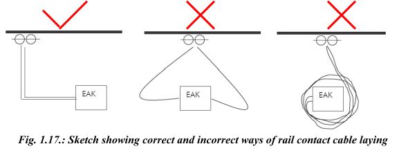
12. The rail contact cable wires must be twisted in pairs to improve EMC.
13. To earth the rail contact cable screen, remove the cable insulation for a length of maximum 45mm from the end of cable. Never remove insulation from any other part of cable.
14. Always use WAGO screwdriver to work with the WAGO connectors
15. Armour of quad cable connecting DP to location and location to relay room should be earthed at relay room only.
16. Ensure that twisted pairs of quad cable remain twisted right upto the terminals, no coiling to be done.
17. Take all the measurements whenever the DP is adjusted.
Log Sheet
This should be periodically updated and kept as future reference.
I want to get all signalling related equipment details
I want to get all signalling related equipment details.
cbtc concept related