Railway Single Section Digital Axle Counter CEL DACF 710 A & DACF 710 P
The system comprises trackside counting units, installed at both ends near the detection points on the track. No separate evaluator is required. Two versions available
(i) DACF 710 P (Phase reversal type) The DACF 710 P is not affected by the push trolleys having 4 spoke and 8 spoke wheels; and rail dolly. A trolley suppression track circuit is not required. It counts the following push trolleys: (a) Push trolley with the perforated wheel; (b) Dip lorry and (c) Motor trolley.
(ii) DACF 710 A (Amplitude Modulation type) The SSDAC remains unaffected with all types of insulated push trolleys but goes into the disturbed state (ERROR condition) for non-insulated trolleys. A trolley suppression track circuit is required.
Components of DACF
The CEL DACF system consists of the following units
Axle detectors
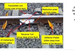
1. Transmitter (TX) coils – 2Nos. fed with 21 kHz and 23 kHz carrier signals
2. Receiver (RX) coils – 2 Nos. to receive the transmitter signal The Rx signal is phase modulated with each train wheel passing over the detection point.
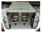
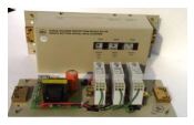
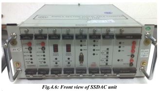
Trackside electronic unit (SSDAC)
The SSDAC unit comprises total 8 cards namely:
Card No.1 & 2 – Signal Conditioning Card
Card No.3 & 4 – Microcontroller logic blocks (2 Microcontrollers)
Card No. 5 – Event Logger Card
Card No. 6 – Modem Card
Card No. 7 – Relay Driver Card
Card No. 8 – Power Supply Module (DC-DC converter)
Vital relay box
The VR box consists of a dual relay i.e VR & PR relay of Q style, 24V, and 1000 ohm. It is provided in the trackside location box along with the SSDAC unit.
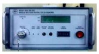
SM’s Reset Box
– 1 No. for common resetting (when used in station area/platform lines)
– 2 Nos. for independent resetting (when used in block sections)
The reset box consists of the following:
i. The LED indications
a. Section Clear – Green indication.
b. Section Occupied – Red indication.
c. Power ON – Yellow indication.
d. Preparatory Reset – Green indication.
e. Line Verification – Yellow indication.
ii. SM’s key actuator.
iii. Reset Pushbutton (Red color). Fig. 4.2: SM’s Reset Box
iv. Counter for recording the number of reset operations.
v. 20 X 2 LCD display with backlit.
vi. 4 keys keypad for setting the date and time operation.
vii. 9 pin D-sub connector on the motherboard of reset box, used for downloading the data for analysis purpose.
Surge Voltage Protection Device This Surge Voltage Protection Device is provided to protect the equipment from surge voltages. This device is to be installed at each location along with every SSDAC unit.
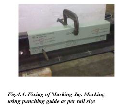
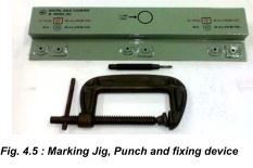
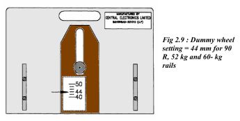
Installation of Tx and Rx coils after replacement of rail Marking and drilling holes on web of rail 3 holes of 14 mm dia.on the rail web 0-170-340 mm at 86 mm from the top for 90R rail and 88 mm. from the top for 52 Kg/60Kg. rail.
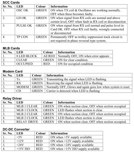
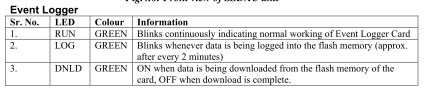
LED indications on SSDAC unit
The LED indications are provided on the facial plate i.e. on the front side of different modules of SSDAC viz. SCC cards, MLB Cards, Modem Card, Relay Driver, DC-DC Converter, and Event Logger to indicate OK or Error conditions. These are as follows:
Maintenance
Recording of Signal levels:- For maintenance of Single Section Digital Axle Counter various parameters are to be checked periodically. The various signal input and output levels and their limits which are to be recorded and adjusted to correct levels wherever necessary are given in the following tables:
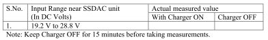
24 V DC Supply (Battery)
Measure the DC 24 V input to the system with charger ON, charger OFF condition with all the units connected (i.e. on load) or using dummy load.
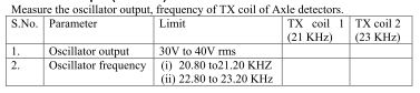
Oscillator Output (TX Coils)
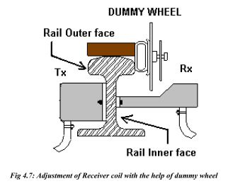
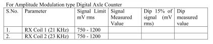
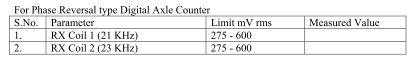
Receiver Coil Output
Measure the RX coil signal output with and without a dummy wheel.
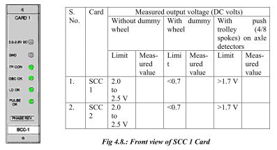
SCC Cards (Cards 1 & 2)
Measure the DC voltages at monitoring sockets of SCC cards 1 & 2 with respect to ground.
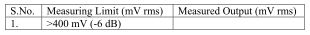
Modem Output (Card 6)
Check and record the modem signal output of SSDAC during the normal working conditions of the system.
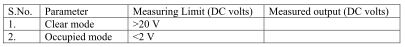
Relay Drive (Card 7)
Check and record Relay drive output to the Vital Relay with section clear and section occupied condition. (This may be checked across R1 & R2 of relay coil in vital relay box).
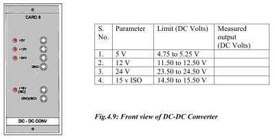
DC-DC Converter Card (Card 8)
Measure the DC-DC Converter output voltages with respect to respective ground for 24 V DC input fed to the SSDAC.
Maintenance Schedule (Monthly)
(i) Tx & Rx Coil Axle Detectors (At site)
1. Measure the TX coil (21 kHz & 23 kHz) signal levels and record them. These measurements are to be tallied with the previous readings. These should be within the specified limits and should not change more than 10%.
2. Measure the Rx coil (21 kHz & 23 kHz) signal levels and record them. These measurements are to be tallied with the previous readings. These should be within the specified limits and should not change more than 10%.
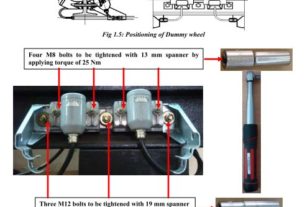
3. Check the M12 Bolts & Nuts of web mounted TX & Rx coil Axle detectors. All the nuts should be in tight condition.
4. Check and tighten the deflector plates if found loose.
(ii) SSDAC Unit (At site)
1. The 2.2V DC signal levels of card 1&2 of the SSDAC Counting Units are measured and
2. recorded. The level should be between 2.0 to 2.5V DC.
3. DC-DC converter output voltages should be measured and recorded. The outputs
4. measured should remain within the specified limits and match with the previous readings.
5. The modem card output should be measured and recorded. The reading should match
6. with the previous readings
7. Check the relay driver output and it should be >20 V DC. This reading is recorded.
8. Ensure that the screws of modules are tight.
9. Ensure that MS circular connectors are tight.
Power Supply (Battery Room & Site)
1. The 24V DC power supply should be measured and recorded. The 24V DC should remain within specified limits.
2. Inspect the battery charger and check its charging current and ensure it is properly
3. charging the battery.
4. Any interference with the power supply and connections of SSDACis likely to cause failure.
5. This should be done only after ensuring that no train is occupying or approaching the section.
Inspection of Reset Box (SM’s room)
1. Monitor the reset box while the train is occupying the section. The occupied (red)
2. LED should be glowing.
3. When the train clears the section, the clear LED (green) glows.
4. The Reset to the system is controlled through the key actuator & Reset button of
5. reset box. This should not be disturbed.
6. The LCD displays all the information regarding the system. (Please refer to Handbook on Troubleshooting of Digital Axle Counter Section IV)
General
1. Check all the cable connections on the CT board of the apparatus case at both locations.
2. Ensure that these are in tight condition.
3. Check the deflector plates of the Axle detectors are in normal position. If found loose this should be properly tightened.
Repair of Faulty Cards
1. Before declaring any card is faulty, the fault should be analyzed and confirmed.
2. Repair of cards is a highly technical job and is not possible at the site. Hence Railways
3. should not carry it out. The card should be sent to CEL for repair.
Resetting Procedure:- 4.9.1 In the station area
Common resetting
The common resetting of both SSDAC units is to be carried out when used in the station area for platform lines, yard lines, etc. Last vehicle (LV) proving is used in conjunction with a reset box if required. Resetting operation
1. Insert SM’s key, turn right and keep pressed.
2. Press the Reset button for 2 seconds.
3. Release SM’s key and Reset Button.
4. Turn left, remove SM’s key, and keep in safe custody.
With the above operation
1. 48 V DC from reset box is extended to SSDAC unit.
2. Reset command is generated in MLB1 and MLB2 cards (Cards 3 & 4).
3. The SSDAC units are reset and counts become zero.
4. The SSDAC units attain the preparatory reset state.
5. The PR & PPR relays pick up and Prep. The reset indication glows on the reset box.
6. The reset counter reading increments by 1 count.
7. After one pilot train is passed in the section the system becomes normal.
8. Vital Relay picks up.
Note: Reset command to Micro-controllers will not be generated if the system is in a clear/preparatory/occupied state. The system can be reset if it is in an error state or out counts were registered after the occupied state.
4.9.2 In Block Section – Independent resetting
The independent resetting of SSDAC units at each station is to be carried out when used in Block Sections. Sometimes SM’s key and button contacts are extended to a remote location for resetting purposes.
Resetting operation
1. Insert SM’s key, turn right and keep pressed.
2. Press the Reset button for 2 seconds.
3. Preparatory LED starts flashing.
4. Release SM’s key and Reset Button.
5. Turn left, remove SM’s key, and keep in safe custody.
With the above operation
1. 48 V DC from reset box is extended to SSDAC unit.
2. Reset command is generated in MLB1 and MLB2 cards (Cards 3 & 4).
3. The SSDAC units are reset and counts become zero.
4. The SSDAC units attain the preparatory reset state.
5. The PR & PPR relays pick up and Prep. The reset indication glows on the reset box.
6. The reset counter reading increments by 1 count.
7. After one pilot train is passed in the section the system becomes normal.
8. Vital Relay picks up.
What i do not realize is actually how you are no longer really much more smartly-favored than you might be now.
You’re so intelligent. You recognize thus significantly in terms of this topic, made
me in my opinion believe it from so many varied angles.
Its like women and men aren’t interested unless it’s one thing to accomplish
with Woman gaga! Your individual stuffs excellent.
All the time deal with it up!