Railway Signal positioning & Visibility
Signal Positioning and Visibility GE/RT8037 – Signal Positioning and Visibility This Standard contains mandatory requirements for positioning signals and indicators to ensure adequate viewing and clarity of meaning for drivers. GE/GN8537 – Guidence on Signal positioning and visibility. This document supports GE/RT8037 and provided guidence on the requirements for positioning of signals and indicators.
Assessed minimum reading time
The sum of the times assessed to be essential in order for a driver approaching a signal to:
a) detect the presence of a signal.
b) identify the signal as being applicable to the b) identify the signal as being applicable to the driver.
c) observe the information presented by the signal.
d) interpret the information to determine what action, if any is required.
Minimum reading time shall be determined for each signal except the following types:
a) Signals where trains can only start from rest (terminal platform starter etc.).
b) Signals that can only display a stop aspect (for example fixed red or a stop board).
c) Signals where all approaching trains are required to proceed at a speed which allows them to stop on sight ( for example independent. PLS) However minimum reading time not required to be assessed for the above signals but minimum reading distance should be determined.
Readable
An aspect or indication is readable if, under clear weather conditions by day and by night, persons meeting the minimum eyesight requirements and always able to identify the aspects and indications displayed when viewed form the driving position. Clear weather conditions means daylight visibility of 1000m or
better better
Required Reading Distance: The distance before the signal determined by the signal sighting committee that is to be provided for sighting a signal by the driver of an approaching train.
The principle requirement of a signal positioning is
a) the driver of an approaching train has sufficient time to identify, observe and interpret the information being displayed.
b) the information being presented is clear and unambiguous unambiguous.
c) the risk of reading the wrong signal is minimised.
d) the presentation of information displayed to the driver is such as to avoid information overload.
Determining the assessed minimum reading time (MRT)
The assessed minimum reading time shall not be less than eight sceonds travelling time before the signal.
The assessed minimum reading time shall be greater than eight seconds where there is likelihood of misread or failure to observe a signal.
Circumstances where this will applies include but not limited to the following
a) the time taken to identify the signal is longer. a) the time taken to identify the signal is longer.
b) the time taken to interpret the information presented by the signaller is longer.
c) there is a risk that the need to perform other duties could cause distraction from viewing the signal correctly.
d) the control of train speed is infuenced by other afctors.
Longitudinal positioning of signals
The longitudinal position of signals shall be selected so as to ensure that they meet the readability requirements and taking into account the requirements for
a) signal spacing ( see GK/RT0034)
b) provision of signals (see GK/Rt0032)
c) positioning of signals used to control movements onto c) positioning of signals used to control movements onto occupied lines (see GK/RT0044) In order to meet readability requirements it may be necessary to reposition signals from their designated position but this may introduce eneven spacing between signals. GK/Rt0034 provides tolerances on variations in signal spacing.
Minimum Reading Distance (MRD):
The location on the trains approach to the signal at which the assessed minimum reading time commences.This will usually calculated using the permissible speed applicable at that location. speed applicable at that location.
Achievable Reading Distance:
As far as possible and practicable hazards and obstructions to the drivers view of the signal shall be removed to achieve maximum reading distance.
Signal Sighting Process
Consideration of signal sighting issues shall be properly co-ordinated with the overall scheme design process. As part of the signalling design production and overrun risk assessment processes the proposed position and form of each new and altered signal should be form of each new and altered signal should be produced.
These details should be submitted to a signal sighting committee in order for an on site evaluation of the proposals to be undertaken.
Signal sighting committee include all the expertise in Engineering, Operations, train driving, local knowledge.
Role of signal sighting committee
There are three distinct roles for a signal sighting committee, depending upon whether the work is related to:
a) new, modified and reposition signals review preliminary sighting proposals produced by the designers. identify any alterations or additions are required identify any alterations or additions are required make recommendations about the position of a signal.
When satisfied, each member shall indicate in writing their agreement with the proposed sighting details, and the committee shall recommend the sighting details to infrastructure controller for approval.
Role of signal sighting committee
b) SPAD investigations: SPAD investigation for existing signals.
c) Linespeed increase: Assess the signal for compliance with the standard GE/RT8037 at the proposed speed. Where necessary make recommendations regarding improvements that shall be made to the signal before introduction of the higher speed. introduction of the higher speed.Signal sighting committee shall also consider the position of
a) Signal post telephone
b) PSR boards
c) AWS inductors.
Fundamentally, the role is in fact the same in all the above cases that of assessing the signal or proposed signal demonstrating fit for purpose.
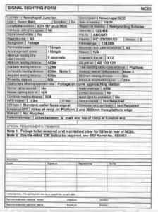
Signal Sighting Form
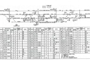
The signal sighting form is intended to record all the physical design features as agreed by the committee. The form should include a drawing showing the position of all the signal elements, the type of structure and dimensions to the running rails. All signage that is to be fixed to the structure be shown All signage that is to be fixed to the structure be shown so as to clearly identify their positions relative to the signal. Space should be provided for signatures of all the committee members, the checker and the person authorising the plan for the infrastructure controller.
Signal Sighting Form Sample
Requirements for positioning and visibility of signals Each signal shall be positioned on the left hand side of the line.
The signals shall be positioned on right side of line if
a) readability is improved and SPAD risk is reduced. reduced.
b) For stop signals, the signal is readable by drivers of trains stationary in the normal stopping position at the signal
c) There is no line immediately to the right of thensignal.
Signals on parallel lines:
Where lines running parallel to each other are signalled in the same direction and drivers on one line can see the signal(s) on the parallel line(s), the signals for each line shall normally be placed at the same longitudinal positions as those on the parallel lines. This is called ‘parallel positioning’ of signals. This is called ‘parallel positioning’ of signals. Signals shall be regarded as parallel if they are within 20 metres of each other longitudinally.
Close-up viewing of the signal:
For signals capable of displaying a stop aspect, all elements of the signal shall be readable from the driving cab with no interruption of view between 40m from the signal and the closest point at which a driver is expected to bring his train to a stand at the signal at danger.
There are series of factors that can effect this, for example:
a) the lateral position of the signal.
b) the optical design of the signal.
c) restrictions of view caused by the cab design.
d) how close to the signal the train can be expected to stop.
Visibility of signals on other lines:
Signals shall be positioned and aligned so as not to cause confusion in the correct observation and interpretation of other signals by drivers on other lines and also ensure that a driver has adequate visibility of signals on their line. On parallel lines signalled in the same direction, On parallel lines signalled in the same direction, consideration shall be given to the provision of a means by which a driver can more readily identify the signal that is applicable to their train. For example Line identify plates are used in several complex locations to provided assistance to driver.
Read Through:
Considerations shall be given to the risk of a driver reading through to a signal The most common read through problem exists where a driver can see beyond the nearest signal to a less restrictive aspect, which in some circumstances takes precedence in the drivers mind.For example an precedence in the drivers mind.For example an automatic signal beyond junction or level crossing. On straight lines where several signal sections are visible to the driver, a signal can become obscured( by OLE masts) such that driver can see the near signal , not see the next but able to see one or more after that.
Form of signals:
Successive signals for the same direction of the traffic flow shall be reasonably consistent in form.The above facilitates correct observation by the driver about the information presented. Colour light and semaphore elements should not be Colour light and semaphore elements should not be intermixed on a signal, except that is permissible to use Alphanumeric route indicators in conjunction with semaphore signals.
Lineside signs in the vicinity of signals:
Lineside signs shall be positioned so as not to create unnecessary distraction from the driver’s primary role of observing signals.So far as reasonably practicable, signs shall not be positioned between the signal and its associated AWS or within 50m beyond the signal. or within 50m beyond the signal. If the sign has AWS equipment associated with it, the sign shall be positioned such that the AWS for the sign does not fall between the signal and its AWS equipment.
Positioning of subsidiary signals:
Subsidiary PLSs shall be positioned immediately below the red main aspect It is permissible for the subsidiary PLS to be positioned immediately to the left of main red aspect, when the signal is to the left of the line to which it applies, or to the right if the signal is to the right of the line to which it applies, if either route indicators are associated with the PLS or route indicators are associated with the PLS or The effect of placing the PLS beneath the red aspect would be to make the red aspect less readable. Where route indicators are associated with a subsidiary signal, they shall usually be positioned immediately above the PLS Route indicators associated with an Independent PLS shall usually positioned immediately above the PLS.
Positioning of co-acting signals:
The longitudinal separation of the co-acting signals shall not be more than 2m. It is permissible for co-acting signals to be positioned on opposite sides of the line to which they apply. on opposite sides of the line to which they apply. The lateral position of the co-acting signals shall be such that there is no possibility of a driver mistakenly thinking that either applies to another line.
Banner repeater signals:
Banner repeater signals provide only limited information about the aspect of the signal ahead, which in turn restricts their usefulness as a means of the reading time of main signals. banner signal should be readable by the driver for a minimum five seconds. The main signal shall become visible when the driver loses sight of the banner repeater.
OFF indicators:
Off indicators shall be provided in situations where the guard or person incharge of a platform is unable to see the platform starter signal or banner repeater signal. Banner signal is not a suitable substitute for an “OFF” indicator. indicator. Where OFF indicators are provided on bi-directional platforms or platforms equipped with mid-platform signals, the OFF indicator shall additionally indicate the signal or direction of movement to which it applies.
CD/RA indicators:
CD and RA indicators, where required shall meet the following:
a) Co-located with any platform starting signal provided and with any banner repeating signals.
b) They should be readable by the driver b) They should be readable by the driver when stationary at any normal stopping position
c) They should be readable by the person incharge of the platform Where necessary, duplicate indicators shall be provided to achieve the above.
