Booster Transformers/return conductor (BT/RC) system |Automatic Power Control
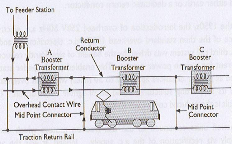
■To improve matters further current must be forced or driven through RCs and ideally 100% of return current is required in the RCs. This is achieved through Booster Transformers
■Booster transformers are installed at overhead line overlap spans generally at intervals of 3.2 Kms
■Primary winding is connected in series with 25 KV overhead line conductor system and secondary wining in series with associated return conductor
■Return conductors are supported from the overhead line structures by insulators and are connected to the running rails midway between BT locations, and to the neutral of the incoming 25 KV supply at the feeder stations (bonds are called mid point connectors).
■Effect of BT
– Produce current in RC which approximates catenary current in magnitude but is in antiphase (opposite direction of flow in secondary winding)
– Secondary circuit of BT is low impedance loop via RC, adjacent mid point connectors and rail/earth
Each BT deals with a 2 mile section
Maximum suppression of induction is achieved with a traction load located at a mid point connector, and the minimum suppression when traction load is at a BT.
With load at mid –point connector, BT/RC system can reduce induction by as much as 95%

![]()
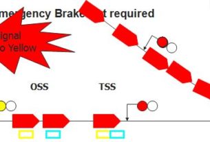
Automatic Power Control
1. Neutral Sections isolate supplies of adjacent feeder stations
2. Automatic Power control (APC) is a system that automatically powers down the traction unit and disconnects it via on board circuit breaker before it enters the neutral section, and reconnects it after passage
3. This is done to prevent drawing of a damaging arc, by the traction unit, if it remains powered in the neutral section APC uses permanent instructors on sleeper ends either side of neutral section which are sensed by bogie mounted receivers on the traction unit.
4. Same permanent inductor and receiver equipment is used as for Automatic Warning system (AWS)
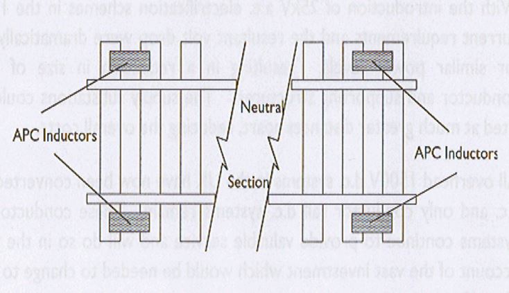
Typical Neutral Section

It’s done very well