Power Supply Railway Signalling Lightning Protection Earthing
What is a Power Supply?
1. Electrical supply used for Signaling purposes. Different types of equipment need different voltages.
2. Supply is extended by the Electrical department based on the requirement of signaling.
3. Signalling has to provide the details of locations and maximum load at each location.
4. Based on these requirements the main transformers and the feeder cables are designed.
5. At each location the distribution is the responsibility of signaling.
Various supplies are used in signaling.
- 50 VDC – standardized for new signaling circuits with BR relays
- 24VDC – used in old installations with 24V relays and also for standard AWS circuits.
- 12VDC for old shelf type relays, lever locks, SPTs and old AWS circuits.
- 120VDC for point operation
- 110VAC for all general purposes of signaling.
- 140V AC used in SSI
Supplies above 110V AC are considered to be high voltages which require proper protection. Signal staff are authorized to handle supplies above110V AC.
Electricity at Work Regulations (1989) made under the Health and Safety at Work Act 1974.
- Employers and Employees are required to take suitable precautions when working with or near to electrical equipments
- All electrical and electronic equipments are required to comply to these regulations.
The main requirements are:
- Protection from Direct Contact
- Protection from indirect contact
- Use of appropriate equipment
- Over current protection
- Ability to disconnect the supply
- Sufficient working space
- Competent staff
- Accurate documentation
Distribution of mains power
- Ring system is provided to feed the mains power to any Relay Room / loc from a feeder station.
- Each location has facility for isolating itself from the supply.
- Facility to be provided for isolating sections for maintenance / fault finding activities.
- Load on the feeder is calculated before introducing a new location on the supply.
- Load distribution and feeder cables are designed to ensure that a minimum of 90% supply is available at any point in case of ring breakage
Fuses and Circuit Breakers
- Fuses are used to protect end equipment from high currents which can damage the equipment. Similarly circuit breakers are utilized. At the same time they isolate a fualty equipment from other equipement/circuit.
- Fuses have to be replaced if they blow off. Circuit breakers can be reset.
- UK railways have Porcelain type fuse holders and also Enterlec type. Fuses may be of varying values depending on requirements. Typical values are 1A, 2A, 3A, 4A , 6A , 10A , 15A etc.
- CM type fuse holders are used for outgoing feeds / supplies to track for track circuits etc. They are also of various values – 32A, 63A ,100A etc.
Enterlec type fuses : representation
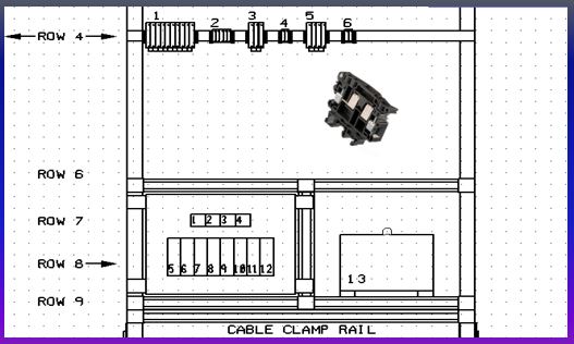
Porcelain fuse: Representation
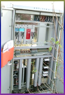
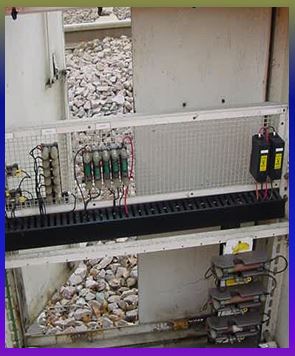
CABLES AND POWER FEEDERS
- Cables are used to run 110V AC Power supply between the locations/cases.
- 2 core 2.5 sq.mm (f) type B2 are used.
- Internal power wiring is done by single core cables
- We generally use 1 core 2.5 sqmm (RD or BK) for 110V
- Power feeder locations are provided at regular intervals generally nearer to a RR.
- It is important that the voltage variation is accounted for and as per Standards a variation of +/- 10% over the supply voltage is permitted.
INDICATIONS
- Generally the failure of power is indicated to the signaller by means of an audible and/or visual alarm.
Earthing
Requirements for Earthing
- All electronic equipment needs to be earthed to protect against Electrical Surges. So to protect the equipment from surge earthing is provided is known as a fast transient earth (FTE).
- There has to be only one earth at any given location and earth connections have to be bonded together.
- Any other earthed signaling equipment, loc box is present within touching distance of other metal works, then it is required to be bonded together to avoid the possibility of a potential difference between the items.
- FTEs should have low inductances.
- Typical values may be 10 ohms
- As a direct requirement all location cases within 2.0m of each other, one of which is earthed, are required to be bonded together to avoid the possibility of a potential difference between 2 metal works causing a flow of current when any person accidentally comes into contact with both cases simultaneously.
Lightning Protection
What is a lightning strike? – A stroke of a lightning flash attaching to equipment.
Lightning protection system – Whole system of conductors is used to protect equipment from the effects of lightning.
What to do for protection? – Provide a direct and low resistance path to the earth for the lightning currents. Concept of FTE with R=10 ohms or less.