रूट रिले इंटरलॉकिंग, रेलवे सिग्नल इन हिंदी, ट्रेन सिग्नल, रेलवे ऑपरेटिंग मैनुअल इन हिंदी, रेल वायर क्या है, Signal button relays,Route button relays,Point button relays,Common button relays,button relay circuits,Design Principles
Railway Circuits Diagram Signal button relays। Route button relays। Point button relays। Common button relays
1 button relay circuits
We have studied in Chapter No.7, the various features provided in the “Control cum Indication Panel”. Every main and shunt signal has a button provided at the foot of the signal symbol on the panel. The route buttons are provided in the middle of the track configuration for each route. These buttons are also known as exit buttons or destinations buttons. Point buttons are provided at the point configuration. The various common buttons such as WWN, EWN, EGGN etc. are fixed on the top of the panel.
All these buttons are differently colored for easy distinction. Each button has a button relay. Whenever a button is pressed, the button relay is energized and remains energized till the button is released and restored back to its normal position. In case the pressing of the button is prolonged or the button fails to restore, a failure indication will appear on the panel. The various buttons are grouped as follows and the button relay circuits are provided accordingly:
1 Signal button relays
2 Route button relays
3 Point button relays
4 Common button relays
2 Design Principles
1 The button relays circuits are so designed that only one button relay of that kind can energize at a time. This simplifies the interlocking.
2 Each button relay circuits will have a “common buttons normal checking relay (NCR)” which is normally energized proving the back contacts of all the button relays of that group.
3 The Station Master Control (SMR) is provided on all the groups excepting the signal button relays group-. This is so to enable putting back the signal back to danger in case of emergency by any person in the absence of the SM.
3 Signal button relay Circuits
It may see that whenever any signal button is pressed, the concerned button relay picks up. The circuit is so designed that any button relay picks up only if all other button relays are de energized. The common signal buttons normal checking relay (GNCR) is normally energized proving the back contacts of all the signal button relays. It is a slow to release relay by about 5 to 7 seconds so that during normal operation of the button and its release, the GNCR does not drop and give any false indication of failure. In case the panel operator prolongs the operation of the button beyond this time, this relay drops and gives a bell warning forcing the operator to release the button.
In case the button fails to restore or the button relay fails to de-energize, GNCR drops and gives a visual failure indication as well as a bell warning to attract the attention of the panel operator to the failure. The bell warning is stopped by pressing an ACK. Button, while the visual indication persists till the failure is rectified. The relay is made slow to release with the help of the 3000MFD capacitor and a 100 protective resistance connected across the relay.
It may be seen that in this circuit the SMR control is not provided for the reason already mentioned.
4 Route button relay circuits
The circuit is similar to GNR circuits. Any route button relay can be operated only by an authorized person namely Station Master or Panel Operator. The buttons normal checking relay in this case is UNCR, which is a slow to release relay as GNCR and its function is the same as that of GNCR.
5 Point button relay circuits
The design of the circuit is similar to route button relay circuits. Here also the authorized operation is ensured by SMR relay. The button normal checking relay is called as WNCR which does the same function as that of GNCR and UNCR. The crank-handle button relays are also grouped and their circuits designed on similar lines. The NWWN, RWWN and EWN button relays are also shown and the circuits are self explanatory.
6 Common button relay circuit
The following common buttons for the entire station are grouped in this circuit.
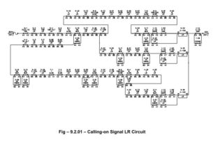
a) CO GGN – Calling on signal button
b) EUYN – Emergency Route Release button.
c) RRBUN – Super Emergency Route Release Button
d) GRN – Common (General) Slot Return button.
e) GBN – Common (General) Slot button
f) EOVN – Emergency overlap Release button.
Here again only one button relay can energize at a time and can be operated only by an authorized person (SMR) The emergency signal cancellation button (EGGN) is a press to break contact unlike the other buttons which are press to make type. Through the normally closed (NC) contact of the button, EGGNR remains normally energized. There is no SM‟s control of this relay as this relay is required to throw the signal to danger in case of emergency by any person. With the “SM‟s Key-in”, SMR relay is normally energized, enabling the various operations on the panel.
The super emergency route is release done by the SM, only with the cooperation of the signal staff. For this purpose, an RRBU lock is provided on the panel and the key for this lock will be in the custody of the signal staff of the station.
Whenever super emergency route release is to be performed, the signal staff has to put his key in RRBU lock and turn it. The RRBUSNR relay picks up and if the SM presses the RRBUN button, RRBUNR picks up through the front contact of RRBUSNR and enables the route to be released.
Very interesting page
Fabulous
thanks
Very nice and very useful
Excellent
tx