Introduction of British Railway Signalling
Essentials of Interlocking
1. The essentials of safe and efficient signalling system are:
2. The concentration of control of points and signals in a signal box.
3.The interlocking of points and signals.
4. Electric/telegraphic communication between adjacent signal boxes.
5. The block signalling system and the regulations for its operation.
6. Its use for passenger trains was enforced by the Regulation of Railways Act 1889.
Need for technical innovation
1. By the end of nineteenth century, British Railway signalling system had evolved into a potentially very safe system.
2. In 1901, for the first time in British Railway history, no passenger was killed in a train accident.
3. Much effort was directed towards ways of improving efficiency and reducing costs.
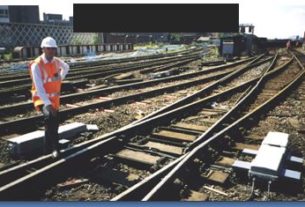
4. The number of signal boxes needed was determined partly by the distance over which a signalman could operate points (finally set at 350yards), partly by workload, and partly by the size of the area which he could visually control.
Problems in busy Railway Stations / Yards were-
1. Large number of signal boxes were needed in the conditions that existed then.
2. Difficulty to keep the signal man fully informed of the nature and timing of the train movements approaching them so that they could take the best decisions regarding the priority to be afforded to any particular movement.
3. Insufficient time to enable signalmen to consult one another regarding proposed movements.
THE OVERALL RESULT WAS
-UNNECESSARY DELAY TO TRAINS AND
-WASTED LINE CAPACITY.
Modern Signalling in British Railways
1. Modern signalling, based on continuous track circuiting, multiple –aspect colour-light signals and route setting of points and signals by a single switch, with the interlocking being achieved by electrical relays belongs to the 20th century.
DEVELOPMENTS
Route Relay Interlocking-RRI
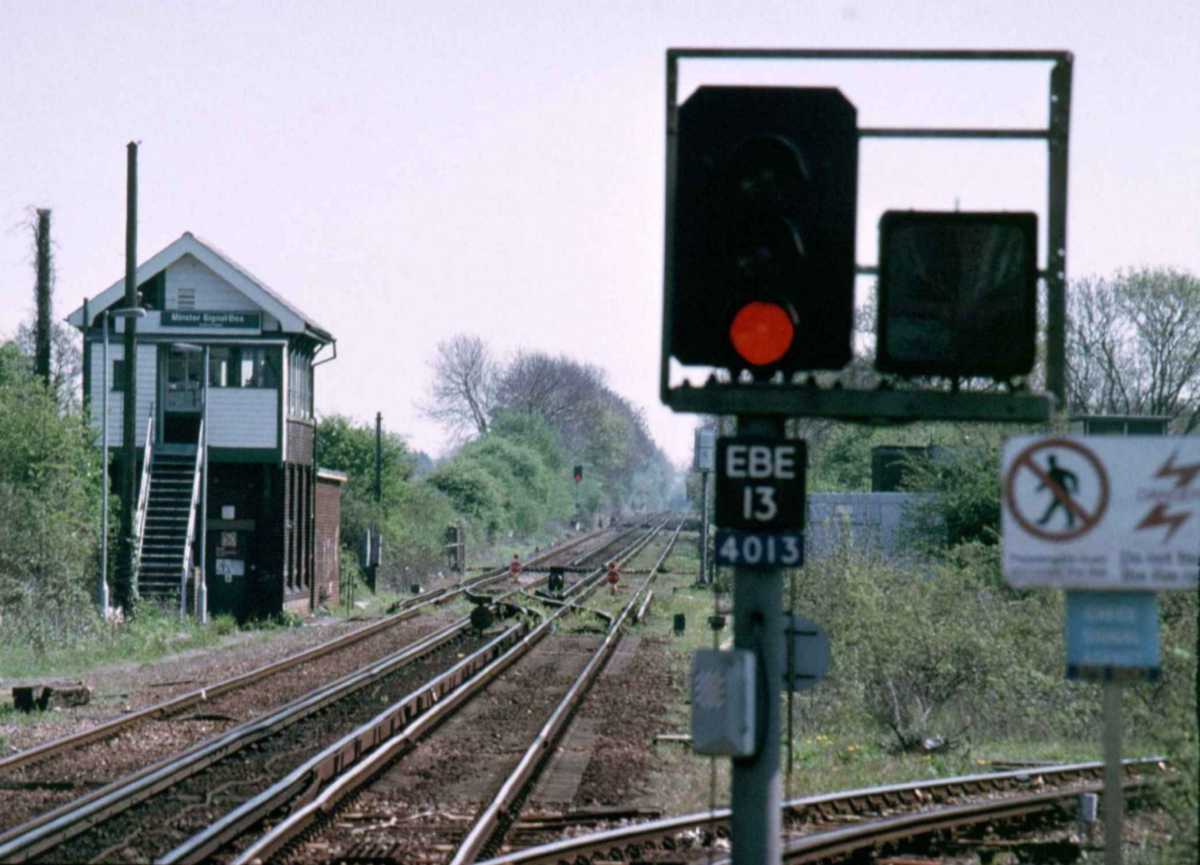
London North East Railway (LNER) first introduced RRI in which interlocking between points and signals was achieved by electric relays rather than by mechanical means @ Thirsk and Northallerton on the East Coast Main line shortly before World War Two. This allowed the signalman to set the points and clear the signal for the desired route merely by turning of a switch.
This enabled a signalman to control a far greater area, much beyond the signalman’s view, than previously, and in order that he should know what was going on in those areas out of sight, he was given a large panel giving a geographical representation of the track layout and signals , etc in his area that showed by a series of lights which way the routes were set and the location of the train and whether signal is cleared or not.
PUSH BUTTON CONTROL
1. Route setting or One Control Switch (OCS )-There was one route or control switch for each route at a junction.
2. Entrance-Exit system. First introduced at Brunswick near Liverpool in 1937.
3. Route set by pressing a button or turning a switch at the start of the route (or entrance to ) and pressing another button at the end of ( or exit from) that route, simplified signalman’s operating equipment.
4. This led to very large combined control and indication panels that were developed from about 1960 onwards. This required the signalman to walk backwards and forwards to operate.
5. So in some signal boxes the panel functions were split so that the signalman could sit and operate the push buttons on a console in the form of a miniature replica with all indications shown on a separate large panel.
TRAIN DESCRIBER APPARATUS
As the areas controlled from one signal box became larger or more complex a system was devised for showing the trains’ description or identity (such as by a four digit identity number on indicators in the signal box)
As the train passes that signal and proceeds towards the next one the TD number automatically steps forwards to be displayed in the next signal section.
1. Very large signal boxes became standardized during 1960s and 1970s and now control most of the main lines and large stations.
2. Technically, there is no limit to the area that can be supervised and controlled from one signal box and natural development has resulted in some very large installations indeed such as London Bridge and Victoria.
3. Each signal box employed many signal men per shift.
4. The term signal box is inappropriate for modern installations and has become “Signalling Centers” or “control Centers”.
REMOTE INERLOCKINGS
In most large signal boxes, the interlocking apparatus controls only points and signals within the immediate vicinity and the interlocking of the points and signals which are farther away is usually dealt within outlying installations, housed in buildings known as remote interlocking. The remote interlocking normally deals with a station or junction area. Communication between the main signal box and the remote interlockings is by cable, either housed in concrete troughing at the line side or buried at a shallow depth.
INTEGRATED ELECTRONIC CONTROL CENTRE (IECC)
This was brought about by changes in traffic patterns and technology. The pattern of train services today is more stable and repetitive than previously and certainly more predictable. Passenger train timetables are now generally based on even interval, the pattern being repeated each hour. Freight trains are rare. This led to development of IECC.
IECC
Distinguishing features from previous generation of power signal boxes:
1. A stable and predictable train service pattern that can be entered into computer
2. Automatic Route Setting (ARS) : Route at a junction is selected by the computer based on the train describer number of an approaching train and a certain amount of priority logic, previously programmed. Relieves signalman of repetitive tasks.
3. Computer driven train describer apparatus acts as information base for the dissemination of train running information, public address announcements, operation of train departure indicators etc.,
4. Several Video Display Units (VDUs) which replace the signalman’s operating/indications panel and require much less space.
5. A change in the method by which the signalman operates points and signals. Instead of using push buttons, he enters commands either by keyboard or tracker-ball.
6. Instead of relays interlocking is dealt with by a computer software programme in conjunction with Solid state equipment. This requires much less space, hence can be housed in much smaller building than a 1960/1970 signal box.
Role of signalman in an IECC
Contrasts markedly with that of a traditional manually-operated signal box. He controls a very large area and he is able to do so because:
1. He can enter his commands quickly and easily.
2. Automatic route setting lightens his workload
3. The visual information of trains, their description and disposition, which is readily available, enables him to determine the priorities and make train regulating decisions quickly and to the best advantage.
Safety which is a major preoccupation of a signalman in a manual box is largely incorporated in the signalling equipment itself. So, signalman can concentrate on his train regulating decisions without the heavy and physically tiring work of the signalman in a manual signal box.
From RRI to IECC
RRI:
Large signal box with routes set on NX principle by switch or push button.
Train descriptions on illuminated diagram panel.
Automatic route setting.
IECC:
Automatic route setting.
Replace large diagram panel by VDUs.
Computer driven train describer equipment.
Replace relays by solid state equipment for interlocking purposes.
Other Advances
SIGNALLING ON SINGLE LINES:
To replace token block working and simplify operation, token less block working was introduced to guarantee that only one train in a single line section using a system of sequential track circuit occupation and clearance to prove that a train has passed a section before a further train could be admitted from either end.
RADIO ELECTRONIC TOKEN BLOCK (RETB):
Economic necessity led to the most recent method of working. It eliminates the requirement of intermediate signal boxes and line side cabling as all movements are controlled from radio from a central point.
RETB
1. Instead of a signalman handing a token, an electronic token is issued to driver by radio and appears on an instrument panel in driver’s cab. The names of the ends of the concerned section also displayed in a window.
2. There are no line side signals, merely marker boards. All instructions to driver are given by radio
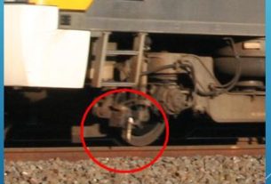
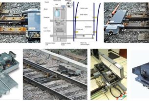
3. Hydro-pneumatic points are provided at the crossing loops. A points indicator to confirm that the points are correctly set. Points can be trailed through without damage by trains leaving the loop in opposite direction.
20th CENTURY Forward
British Railway (BR) signalling is technically very advanced, and its development might be thought of as a series of steps rather than a gradual smooth process. And it is important to remember that although much of BR is signalled by modern methods, there remain hundreds of miles controlled by traditional systems born in the nineteenth and twentieth century, together with a number of signal boxes which represent intermediate stages of development, although latter are disappearing fast.
Assistance to driver
It is essential that the message given by the signal arm or light is observed, correctly interpreted and correctly acted upon by the driver. The interface between signal and driver is vital and the penalty for error is severe, in terms of accidents, unsafe incidents and possible loss of human life. One of the serious and most frequent causes of accident has been the failure of the driver to act upon the warning given by signal at caution resulting in his train passing at high speed and colliding with train in front. This has lead to introduction of:
- Automatic warning Systems (AWS)
- 2. Automatic train protection (ATP)
- Automatic train control (ATC)
ATC/AWS
1. To reinforce the visual message and give audible warning different forms of cab signalling were developed.
2. Great Western’s automatic train control was the first followed by.
3. LMS had Hudd system.
4. Both the above caused the brake to be applied if the driver failed to acknowledge the warning.
5. After nationalization in 1948, Railways modified the Hudd system which became known as AWS Automatic Warning system.
6. Beginning 1958, for over 30 years, often in parallel with the power signal box re-signalling schemes , over 7000 route miles are now equipped with.
BR AWS, representing approx 70% of the total route mileage. Two serious drawbacks of AWS are:
Audible warning does not differentiate and might mislead the driver.
AWS does not monitor the driver’s response to a warning to see that he is braking correctly.
Automatic Train Protection
1. A new system known as ATP was developed to incorporate measures to overcome above drawbacks.
2. It has an on-board computer that receives information from the track about the approach of the train to locations where it must slow down or stop, for speed restrictions or adverse signals.
3. The computer then calculates the braking curve necessary to enable train to slow down appropriately and compares it with the actual speed on the speedometer.
4. If actual speed strays outside braking curve envelope, driver will receive a warning as soon as excess is 3mph. If driver fails to respond sufficiently brakes will be applied automatically as soon as excess is 6 mph.
5. System developed and after trials installed on two routes:
-The Great Western Line from Paddington to Bristol
-The Chiltern Line from Marylebone.
Limitation:
1. ATP is Very expensive and is so costly that the expenditure will be difficult to justify on cost-effective grounds.
ERTMS
1. EUROPEAN RAIL TRAFFIC MANAGEMENT SYSTEMS (ERTMS)
2. Train Protection Development Group is leading research into systems , which when installed could reduce the occurrence and mitigate the consequences of Signal Passed at Danger (SPAD). It involved industry partners and suppliers. It identifies Train protection systems requirements, and matches these with existing, emerging technology, functionality and product availability.
3. The Cullen/Uff inquiry into train protection systems recommended national implementation of the ERTMS and Railtrack along with the industry has identified ERTMS as the future for rail safety.
4. It is also compatible with EU interoperability requirements. Railtrack have played a full part with their European partners and the work on the West Coast Route Modernisation (WCRM) , which is currently under trial underlines their commitment.
5. The industry, in partnership with BR is now formulating an integral ERTMS National Implementation Plan based on European standards and anticipated regulatory requirements.
Need for Line side signals
1. Modern technology can make line side signals redundant by displaying in the driver’s cab all the information they presently convey, but the expense and complexity of converting existing lines to such a system are likely to limit its application
2. Fundamentally , at its simplest, signalling fulfills two major requirements:
3. it keeps trains apart either on the same line or where they cross each other’s paths at junctions &
4. provides signalmen with the facility to make the optimum use of track capacity and keeps delays to minimum.
History has shown that-
It has endless potential for technological development and improvement