Railway Signalling Track Circuit
Introduction
1. A Track circuit is an Electrical circuit of which the running Rail of a Railway track forms a part. It is employed for indicating the presence of Trains and thereby for controlling Signalling and Block equipment. For the device Track circuit, the following truly holds good.
2. ‘No single Invention in the history of Development of Railway Transportation has contributed more towards Safety and Dispatch Control in that field than the Track circuit. Track circuit forms the foundation for the development of practically every one of the intricate Systems of Railway Signalling in use today wherein the Train itself is continuously active in maintaining its own protection’
3. Track circuits are categorized as DC Track circuits, AC Track circuits, and Electronic Track circuits (AFTC).
Railway Signalling DC Track Circuit
Open Loop DC TC: The circuit gets completed when the track is occupied through the net resistance of the vehicle axles occupying the track circuit. The series resistance is so adjusted as to give sufficient voltage to the relay when track rails are shunted by axles. In this type of track circuit, if any connection breaks, its occupation goes undetected. Hence, it is used only for limited purposes where its failure does not lead to unsafe conditions.
What is a Closed-Loop DC track circuit?
In this track circuit, the series resistance is called a Regulating Resistance. It regulates the relay voltage so that it falls below the drop-away value when the track is shunted. The fall is caused by the increased voltage drop across the regulating resistance due to a rise in-circuit current when shunted by the vehicles.
What is an AC track circuit?
A.C. Track Circuits are provided exclusively in DC traction areas confined to Bombay Divisions of Western and Central Railways. It is possible to work A.C. Track circuits with A.C. traction also, provided the track circuit supply frequency does not have even a harmonic relation with the traction power frequency of 50Hz. 83 1/3 Hz frequency is chosen for this purpose and these track circuits are used in A.C. Traction areas including the places where DC electric traction ends and AC traction starts.
AC Track Circuits is two Types:
1. Single Rail AC Track Circuits
2. Double Rail AC Track Circuits
The length of the Single Rail Track circuit is permitted up to 500 meters. The maximum permissible length of the Double Rail Track circuit is 2,300 meters. The cable lead Resistance at the Relay end shall not exceed 12 Ohms irrespective of the length of Track circuits. The feed end cable Resistance shall not exceed 12 Ohms for Track circuits of 2,100 and 2,300 meters and it can be progressively more with reduction of Track circuit length.

AFTC
• The Audio Frequency Track Circuit (AFTC) is the Jointless type of track circuit
• specifically designed to meet the onerous immunity required in AC or DC electrified areas
• against the high levels of interference present mainly due to traction harmonics.
• The equipment is classified as universal since it can be used in AC, DC, or Non-electrified sections and meets all the requirements of the known track circuits.
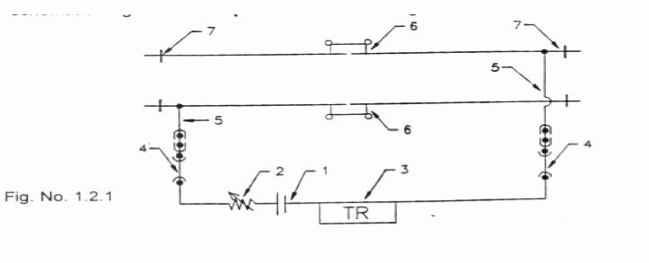
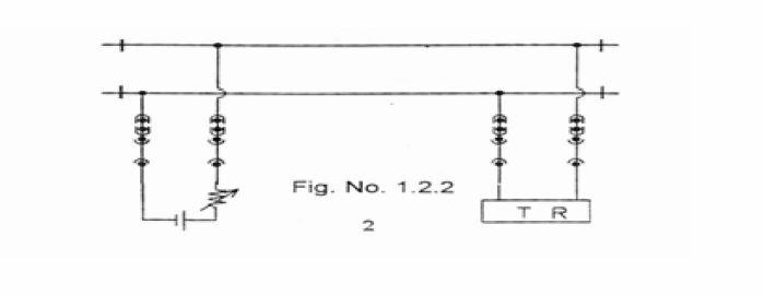
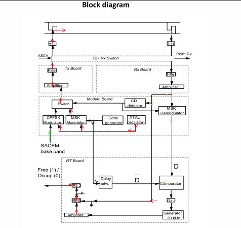
SDTC
• The Smartway DTC is a solid-state, fail- safe system which performs, in a safe way, the train detection, rail continuity detection and track to train data transmission functions within a track circuit (TC) using audio frequency signals
Technical Specifications
• TC length: from 20 to 400 m;
• Transversal conductance: from 0 to 0.5 S/km (2 ohm∙km), LTC=400 m;
• from 0 to 1 S/km (1 ohm∙km), LTC=320 m;
• Maximum shunt resistance 0.5 Ohm;
• Overlap length 7 m (joint length);
• Maximum distance between SER and track connections
• 4.5 km if LTC=350 m, Ballast 0.5 S/km (2 ohm∙km);
• 2.0 km if LTC=400 m, Ballast 0.5 S/km (2 ohm∙km);
• 4.5 km if LTC=280 m, Ballast 1 S/km (1 ohm∙km);
• 2.0 km if LTC=320 m, Ballast 1 S/km (1 ohm∙km)
• Cable type 2×1.5 mm2, 40 nF/km, shielded;
• Data transmission speed: 400 bit/s for train detection;500 bit/s for Sacem;
• Rail continuity control throughout track circuit; Yes
• Maximum number of points in TC 2;
• Power supply 220 Vac ±10% at 50 Hz to 60 Hz;
• Temperature range -25°/+70° in the SER; -40°/+80° in the field;
• Frequency carriers (8nos.) 9.5-11.1-12.7-14.3-15.9-17.5-19.1-20.7 kHz;
• Modulation: MSK ±100 Hz at 400 bit/s (Digicode TC)
• : CPFSK ±100 Hz at 500 bit/s ( data);
• Vital Output 12 Vdc on 400 W or 24 Vdc on 1600 W, insulation 1000 Vac;
• DOT 24 Vdc on 1500 W, insulation 1000 Vac;
• Diagnostic RS232 front or RS422/485 rear connector, at 9600 bit/s, packet
• data protocol.
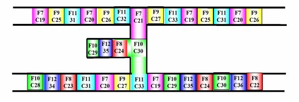
Frequency and codes arrangement
Electrical Joints
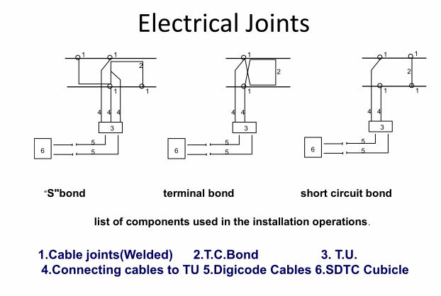
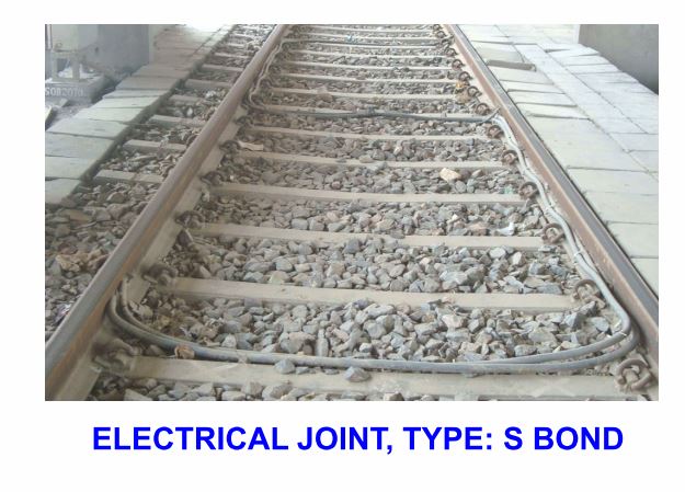
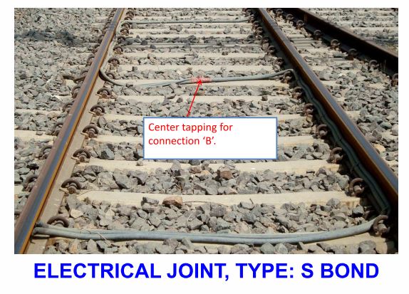
Electrical Joints, S-Bond
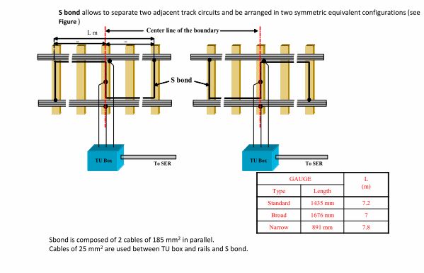
Electrical Joints, Type S-Bond
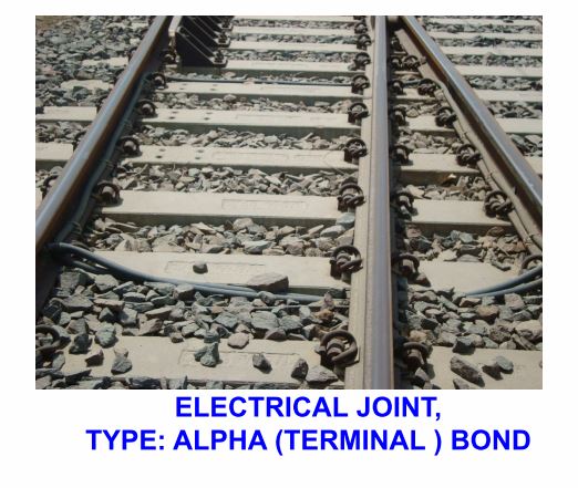
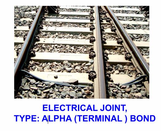
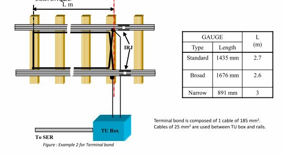
Electrical Joints: terminal Bond
1.Single rail insulation:- Terminal bond allows delimiting the track circuit at a boundary with an Insulated Rail Joint as shown on
Figure The traction current can continue on the next track circuit by flowing through the terminal bond.
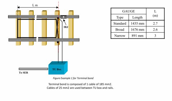
2. Double rail insulation:- Terminal bond allows to delimit the track circuit at a boundary with an Insulated Rail Joint on both rails as
shown in Figure.
ELECTRICAL JOINT, TYPE: DOUBLE ALPHA (TERMINAL ) BOND
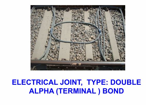
ELECTRICAL JOINT, TYPE: DOUBLE ALPHA (TERMINAL ) BOND

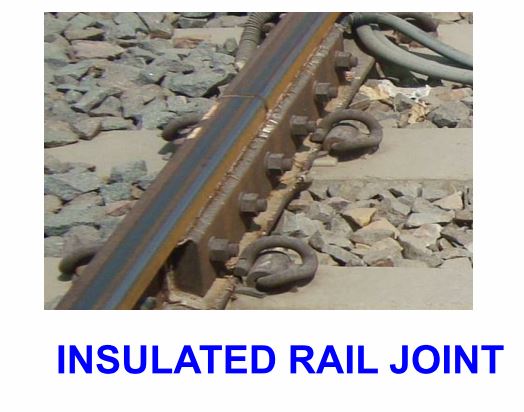
INSULATED RAIL JOINT
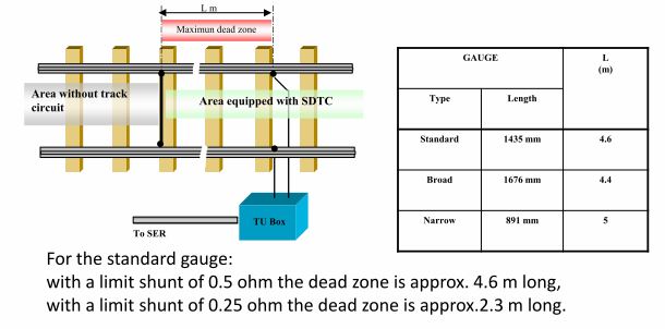
Electrical Joints: Short circuit Bond
Short circuit bond At a boundary with an area without a track circuit, a short circuit bond can be used as shown in Figure
This configuration does not require any Insulated Rail Joints but the drawback is a dead zone whose length is in relation to the limit shunt value.
SDTC principle
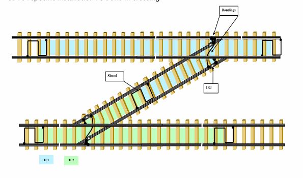
SDTC: specific installation: S Bond in crossing
Please Watch this Video:- https://youtu.be/76XWS4EEPWw
My requirement is DC track circuit bond length 3 mtr. & 5 mtr. in stainless steel (Non-magnetic) Multi strand wire 10 sq.mm 2 layer insulation with SS(Non-magnetic) web pin for fit designing and other side SS (non magnetic) lug. Qty. 230 + 230 each. Inspection by Consignee.