Metro Rail Fiber Optic Transmission System
Fiber Optics Transmission system FOTS
FOTS stands for Fiber Optics Transmission system. It is the transmission system that uses optical fiber as communication media. Thus optical fiber communication is the method of transmitting information through optical fibers.
1. Optical fibers can be used to transmit light and thus information over long distances.
2. They are largely used for telephony, but also for Internet traffic, long high-speed local area networks (LANs), cable TV, and increasingly also for shorter distances.
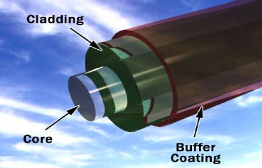
Parts of a single optical fiber
1. Fiber optics (optical fibers) are long, thin strands of very pure glass about the diameter of human hair.
2. They are arranged in bundles called optical cables and used to transmit light signals over long distances.
Optical fiber types
Single mode fibers
Single-mode fibers have small cores and transmit infrared laser light. Some optical fibers can be made from plastic. These fibers have a large core and transmit visible red light from LEDs.
Multimode fibers
Multi-mode fibers have larger cores and transmit infrared light from light-emitting diodes (LEDs).
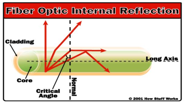
Total Internal Reflection:
Total internal reflection is the principal on which optical fibers work
Fiber optic relay system
Fiber optic relay system consists of the following:
1. Transmitter – Produces and encodes the light signals
2. Optical fiber – Conducts the light signals over a distance
3. Optical regenerator – May be necessary to boost the light signal (for long distances)
4. Optical receiver – Receives and decodes the light signals
Advantages of Fiber Optics:
Compared to conventional metal wire (copper wire), optical fibers are:
1.Less expensive
Several miles of optical cable can be made cheaper than equivalent lengths of copper wire. This saves your provider (cable TV, Internet) and your money.
2.Thinner
Optical fibers can be drawn to smaller diameters than copper wire.
3.Less signal degradation
The loss of signal in optical fiber is less than in copper wire.
4.Non-flammable
Because no electricity is passed through optical fibers, there is no fire hazard.
5.Higher carrying capacity
Because optical fibers are thinner than copper wires, more fibers can be bundled into a given-diameter cable than copper wires. This allows more phone lines to go over the same cable or more channels to come through the cable into your cable TV box.
6.Light signals
Unlike electrical signals in copper wires, light signals from one fiber do not interfere with those of other fibers in the same cable. This means clearer phone conversations or TV reception.
7.Low power Transmitters
Because signals in optical fibers degrade less, lower-power transmitters can be used instead of the high-voltage electrical transmitters needed for copper wires. Again, this saves your provider and you money.
8.Digital signals
Optical fibers are ideally suited for carrying digital information, which is especially useful in computer networks.
9.Lightweight
An optical cable weighs less than a comparable copper wire cable. Fiber-optic cables take up less space in the ground.
10.Flexible
Because fiber optics are so flexible and can transmit and receive light, they are used in many flexible digital cameras for the following purposes:
1. Medical imaging – in bronchoscopes, endoscopes, laparoscopes
2. Mechanical imaging – inspecting mechanical welds in pipes and engines (in airplanes, rockets, space shuttles, cars)
3. Plumbing – to inspect sewer lines
Losses in Optical Fiber Cable
Attenuation loss
Attenuation loss takes place due to coupler, splices, connectors, fiber itself. Attenuation varies with the wavelength of the light
850 nm- 2.5 to 3.0 dB/km
1310 nm- 0.4 to 0.5 dB/km
1550 nm- 0.25 to 0.3 dB/km
Absorption
Absorption is a natural property of glass itself. Losses due to absorption are very large in UV and infra red regions.
Scattering
Loss of the optical energy is due to imperfections in the fiber. Light is scattered in all directions, which causes the loss of power in forward direction, known as Rayleigh scattering loss, takes place due to variations in the density and composition of glass material in the fiber. Rayleigh scattering loss is inversely proportional to four power of wavelength, i.e., for high wavelength, losses will be small.
Macro and Micro bending
i) Macro bending: Loss is caused due to deformation of fiber axis during cabling process.
ii) Micro bending: Excessive bending of the cable or fiber may result in loss known as micro bend loss. For single mode fiber attenuation at longer wavelength like 1550 nm is sensitive to bending.
Fiber Optics Transmission System (FOTS) in DMRC
1. FOTS can be termed as the backbone of DMRC telecommunication network.
2. Fiber optics eases up the data and voice communication or access to various systems at different stations.
3. This network is based on fiber optical cables on both sides of the track.
4. The number of fibers is determined in order to comply with redundancy. The fiber is redundant for security and protection.
5. In case of fiber optic failure, communication can take place via spare fiber while the fiber that is down may be fixed.
The main components of the fiber optic transmission system are:
1. Optical fiber cables
2. Synchronous Digital Hierarchy (SDH)
3. Digital Distribution Frame (DDF)
4. Flexible Multiplexer (FMX)
5. Optical Distribution Frame (ODF)
1. Optical fiber cables are used for the transmission of the data from one station to the other station. Mainly the clock signal from the master clock is transmitted as it helps in the synchronization so that it does not cause any delay in the data transmission and hence the metro trains can run in their required time.
SDH: SDH i.e synchronous digital hierarchy is the technique used for the optical communication. Before knowing in depth about the SDH we should know about the PDH, which was used before the advent of SDH.
PDH (Pleisochronous Digital Hierarchy): PDH uses copper wire to transmit information from one station to other hence, increased I 2 R losses, eddy current losses, current and voltage range limitations and need of repeaters after very small distance, all these factors discouraged the use of PDH. One major drawback is multiplexing and demultiplexing at all stations through which information passes. Troubleshooting is rigorous task due to increased complexity. Due to above mentioned factors, we have switchover from PDH to SDH technology.
Pliesochronous means ‘just synchronous’. In PDH technique different clocks were used and all the clocks cannot be same at same time or synchronous. Also in PDH system, while sending E1 channel, 64kbps additional bits are sent called the stuffing bits and the pointer associated tells whether bits in 64kbps are data or just stuff. If bits are stuff then they are not demultiplexed at the destination.
Limitations of PDH:
1. Not manageable from central network
2. Not completely synchronized
3. Not standardized
4. Less Bandwidth (due to physical media)
Thus to overcome the above limitations we use SDH technique.
SDH(Synchronous Digital Hierarchy):
In SDH, information is transferred through optical fiber. Through this technology we are able to transmit data in terabytes using wavelength 1310 nm. There is no need to demultiplex whole information coming from side by stations. Information to side by stations is passed using STM-4 (Synchronized Transport Module) at 622.08 Mbps.4 STM1 multiplexed in TDM (Time Division Multiplexing) forms STM-4. In this technology repeaters are required at comparatively larger distances.
1. E2=4 E1
2. E3=4 E2=16 E1
3. E4=4 E3=16 E2= 64E1
4. STM1=63 E1
Formation of E1 channel
E1 is the tributary signal for SDH to work.
0 1 2 3 4 5 ……………… 16 ………………… 31
1
:
:
7
256 such data packets give 65536 bps, approx. 64 kbps. 32 time slots of 64 kbps give E1 signal transmitting @ 2.048Mbps. E1 is bi-directional signal Out of these 32 channels 30 are used as voice channel while 2 are used for control and signaling information.
0 16 31
0 – Control data
16 – Signaling data: Carries information about the path E1 goes through.
DDF (Digital Distribution Frame)
The DDF basically provides a flexible way of connecting equipment side to cable side. From the DDF the system working at 2 Mbps rate is directly provided the connections with required number of E1 lines.
FMX/Access MUX
If data rate is less than 64 Mbps then, it is termed as sub-rate. If data rate is more than 64 Mbps then it is termed as super rate. Access-MUX is used for systems requiring transfer rate below 2.048 Mbps. It multiplex the data from the systems operating at the data rates lower than 2 Mbps into E1 lines.
Since no single node will be able to use all the bandwidth therefore, all the data i.e. audio and video signals are multiplexed in order to make maximum use of available bandwidth. FMX is interfaced with Clock system, Cameras, Radio, NP-SCADA, etc.
Optical Distribution Frame (ODF):
GSS and FPS together forms ODF (Optical Distribution Frame). At each node (or station), optical fiber cables are terminated in the GSS (Generic Splicing Self) and are distributed to the system through FPS (Fiber Patching Shelf).
1. From the FPS patch cords, both ends have connectors for connection, are sent to the SDH where apart from being converted to electrical signal, the signals required at the particular node dropped (or extracted) and multiplexed into E1 lines at 2.048 Mbps which are terminated at DDF (Digital Distribution Frame).
2. The DDF basically provides a flexible way of connecting equipment side to cable side. From the DDF the system working at 2 Mbps rate
is directly provided the connections with required number of E1 lines. The systems working with lower rates than 2 Mbps access the network through FMX.
3. The FMX demultiplexes the E1 lines coming from DDF to the lines at the lower rates for use of various systems.
4. There are two GSS, one for up (in Depot direction) and other for down (opposite to Depot). There are 48 trays in each GSS. All fibers
coming from and going to adjacent stations are passing through GSS. Fibers needed at particular station are connected to FPS in zero dB connector (0.3dB loss) through pigtail cords, connector at one end only. These fibers are then passed to SDH. And fibers not
needed at particular station are spliced through.
Splicing is a technique for joining together individual fiber or optical cable sections to forms continuous lines for these long distant links.
Splicing can be done in two ways:
1. Mechanical Splices: This aligns the axis of the two fibers to be joint and physically hold them together.
2. Fusion Splices: This is accomplished by applying localized heating (i.e. by electric arc or flame) at the interface between two butted,
pre-aligned fiber ends, causing them to soften and fuse together. In DMRC fusion splicing is used. Splicing loss is around 0.1dB
In DMRC only 2 fibers for each side are used for transmission in both directions. 24 fibers optical cable is used at elevated stations, 36 fibers optical cable at underground stations and 48 fibers cable at OCC. These figures are selected on the basis of need of information to be received or passed. Equipments used for testing of optical fiber cables are:
1. OTDR (Optical Time Domain Reflectometer)
2. Optical Power Source Meter
OTDR (Optical Time Domain Reflectometer): It is used to calculate the distance between one and other end. Also gives account of
attenuation loss (per km loss) and cumulated (or total) loss.
Optical Power Source meter: Used for point to point testing and total losses also.In case of any short distance breakage, spull (1km long optical fiber cable) is used for connection through splicing. Each station is provided with 4 O-drums to extend the fiber cable in case of any breakage.