RRI Button Circuit
RRI Button Circuit :- points to be operated individually to the required position
After points are set correctly, signal to be cleared.
Route setting system
With a single action.
points initiated.
points operated.
route checked & locked and.
finally signal cleared.
Various route setting systems are in use. NX system is widely used.
Combined Indication & control panel (RRI Button Circuit)
Each signal is associated with a button.
Main signal is provided with a button colored red.
Subsidiary signal is provided with button colored yellow.
All buttons are spring loaded and they return to normal position.
when released after pressing/pulling.
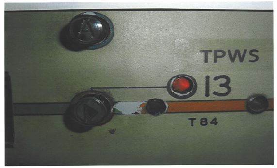
A lamp is incorporated in the base of the button.
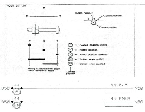
BUTTON SYMBOLS ON PANEL (RRI Button Circuit)
Button contacts
Button contacts – M, F, FM,T, TM
Button contacts used for route setting and releasing
Normal – ‘C’ contact made
pressed – ‘F’ & ‘FM’ contact made
pressed and released – ‘F’ contact breaks & ‘FM’ contact made
pulled – ‘FM’ breaks
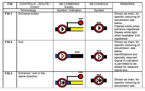
Button indications
First button pressed (at entrance signal) is recognized as entrance button.
Next button pressed (at destination signal) is recognized as exit button.
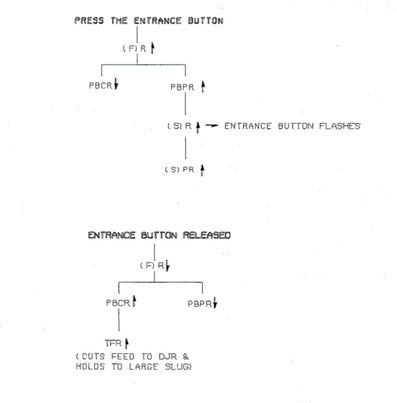
Entrance button pressed – white light starts flashing.
Exit button is pressed within the specified time – light becomes steady provided route is free.
If the exit button is not pressed within the specified time or the selected route is not free – flashing light ceases.
There is no physical interlocking between the buttons like in a Lever Frame. So a button circuit is provided. Apart from route setting and route releasing functions, button circuit fulfills the following functions –
1. To avoid any conflicting route initiation, only one operation should be possible in a group.
2. To prove that pressing of entrance button is intentional that the exit button to be pressed within 7.5 seconds after the entrance button is released.
3. After entrance button is pressed, transfers the operation to exit button
4. Proves that wrong button is not pressed.
5. Proves that operation is completed and ready for the next operation.
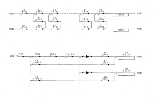
Relays in route setting process
| Relay | Description |
| (F)R ↓ | Energized when button pushed and drops when released. Provided for every button. BR960 Pin Code 212-2x 6F.2B |
| (FM)R↑ | Drops out when button pulled and again energized when button released. Provided for every button. Double wound BR960 Pin Code 060-2x 4F.3B |
| PBCR↑ | Energized when no button pushed in a group. Drops out when any one of the buttons pushed. One for each button ring. BR960 Pin Code 212-2x 6F.2B |
| PBPR↓ |
Energized when any button pushed and drops out when released. One for each push button ring. BR960 Pin Code 212-2x 6F.2B |
| TFR ↓ | Transfer relay. Transfers the button operation from entrance to exit. Energized after entrance button pushed and released. Drops out with either exit button pushed within specified time or after a time delay. One for each button ring. BR931 Pin Code 023-12F.4B |
| Relay | Description |
| (F)R ↓ | Energized when button pushed and drops when released. Provided for every button. BR960 Pin Code 212-2x 6F.2B |
| (FM)R↑ | Drops out when button pulled and again energized when button released. Provided for every button.
Double wound BR960 Pin Code 060-2x 4F.3B |
| PBCR↑ | Energized when no button pushed in a group. Drops out when any one of the buttons pushed. One for each button ring. BR960 Pin Code 212-2x 6F.2B |
| PBPR↓ | Energized when any button pushed and drops out when released. One for each push button ring. BR960 Pin Code 212-2x 6F.2B |
| TFR ↓ | Transfer relay. Transfers the button operation from entrance to exit. Energized after entrance button pushed and released. Drops out with either exit button pushed within specified time or after a time delay. One for each button ring. BR931 Pin Code 023-12F.4B |
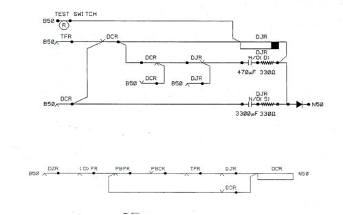
| Relay | Description |
| DJR ↑ | Clear time delay relay. Slow release with two capacitor slugs. Drops away one second after DCR drops, or 7.5 seconds after TFR picks. Drops away one second after DCR drops. One for each push button ring. BR934A Pin Code 063-8F.4B with H/O(D) 470 µF 330W & H/O(S) 3300µF 330 W . |
| Route NLR ↑
(Latched) |
Normal (route) lock relay. Magnetically latched relay is up when the route is normal. To call a route this relay unlatches. Once unlatched, the NLR cannot re-operate until the signal is On and FOAL. One for each route. BR935 Pin Code 011-11F.4B |
| Route RLR↓ | Reverse (route) lock relay. Ordinary acting neutral relay. Contains all the route controls. One for each route. BR931 Pin Code 023-12F.4B |
| NR↓ | Normalizing relay. Energizes when route entrance button pulled or with TORR. One for each entrance button. |
| DZR↓ | Destination invalid relay. Energizes when a wrong button is pressed. One for each push button ring. Energizes when route entrance button pulled or with TORR. One for each entrance button. |
Route initiation –entrance selected
Route initiation circuits

Time delayTFR, DCR, DZR CIRCUITS
TFR energizes after entrance button pushed and released.
DCR re-picks up after exit button released to indicate that operation is completed.
DZR picks up when wrong button pressed.
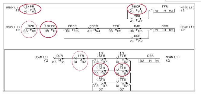
Route initiation circuits
1. DJR drops away 7.5 seconds after TFR picks or one second after DCR drops.
2. DJR↓ releases (S)R & (D)R. Then (S)PR & (D)PR releases.
3. DJR hold switch in relay room is to hold (S)R & (D)R for longer time for Testing.
Route initiation destination selected
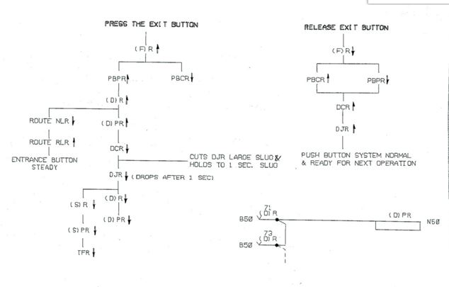
Route initiation – wrong button pressed
(D)R CIRCUITS

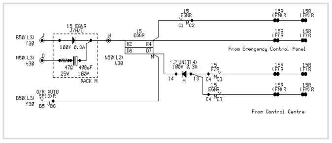
EGNR CIRCUIT
Auto Signals with replacement facility, controlled from two locations. F2R is same as (F)R
Double wound BR960 Pin Code 060-2x 4F.3B
Point switches or keys
Points are operated either by route initiation or by Individual point switches/keys.
Each switch/key is having three positions N, R and C.
During route setting process switch/key is kept in C (CR contact made) position
Switch/Key operated to ‘N’ (NR contact made)- operates the point to Normal.
Point completes operation to ‘N’ even if it is brought back to ‘C’ position subsequently.
Switch/key operated to ‘R (RR contact made) – operates the point to Reverse.
Point completes operation to ‘R’ even if it is brought back to ‘C’ position subsequently.
Corresponding point indications are provided at point switch/key.
Individual signal operation is still possible if the points are available in the required position, even if the switch/key is not in it’s ‘C’ position.
Route identification
When a signal is having more than one route – route on the extreme left as seen facing the signal 43 is identified as ‘43A’. Next extreme left route will be ‘43B’
Where the route is having more than one class of route the class of route is identified by bracketed suffix. e.g. 43A route is having main class, warning class, call-on, and shunt.
43A(M) – main class-full O/L available.
43A(W) – warning class – full O/L available.
43A(C) – Call-on class – berthing track occupied.
43A(S) – Shunt class used for shunting with PLGS.
Route setting

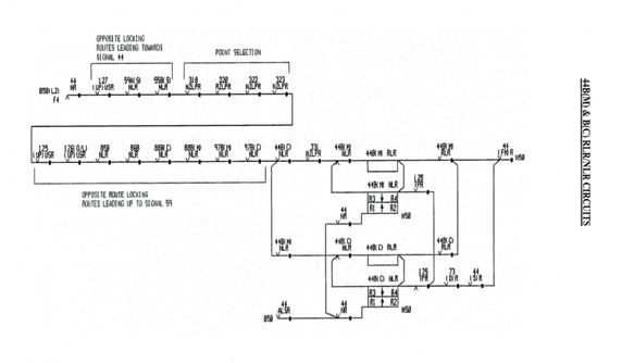
Signal RLR (RRI Button Circuit)
Energised when-
Points are initiated to set to the required position if not already set.
Points will move to the called position
After points are set to correct position and locked the detection relays NWKR/RWKR will pick up.
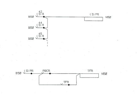
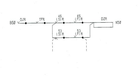
(S)PR & (D)PR CIRCUITS