CBTC Overview Wayside Equipment
This document defines the wayside equipment connected with CBTC.
System Hardware
1. System Management Centre (SMC) at the SCC
2. SMC workstations at the SCC
3. Remote terminals for the SMC ESCC
4. SMC remote terminals at other locations on the wayside
5. Vehicle Control Centre (VCC) located within the SCC CER
6. Snoopers
7. Station Controller Subsystems (SCSs) for points/signals
8. Vehicle On-Board Controllers (VOBCs) for Passenger train
9. Redundant Data Communication System,
CBTC Equipments
SMC Subsystem
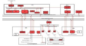
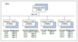
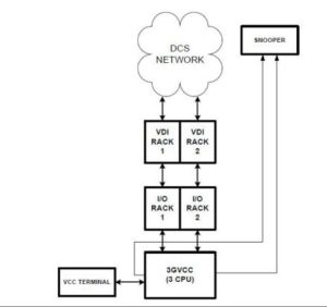
The SMC equipment located at the Service Control Centre (SCC) is a Local Area Network (LAN) based distributed processor control system developed specifically for control room environments. The SMC runs on commercially available off-the-shelf (COTS) computer hardware and software. It serves as the interface between the CBTC system and the Operators.
SMC Lan
Data Communication System (DCS)
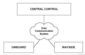
The Data Communication System supports the communications between the different CBTC components located at the SCC, the Wayside and On- Board trains. The communication between different subsystems can be through wired media (copper or fibre optics e.g. between stations and Control Centre) or wireless (between trains and Wayside units).
VCC Subsystem
The VCC is the central element operating all the safety-critical functions of SelTrac. It maintains the moving block separation of trains, ensures the required routes are followed, oversees the train operation and provides all necessary functions to support automatic operation of trains. The VCC is a vital subsystem fully qualified to ensure safety of operation and able to handle failures and emergencies as they arise. Since the VCC subsystem has vital control requirements, check-redundant processor units are used. Availability is achieved through the use of redundant units.
The VCC communicates with each train through the Ethernet Converter Unit and the Thales Radio.
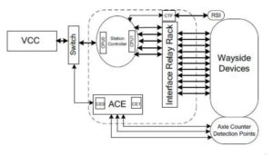
The VCC communicates with the track points and other Wayside devices through the SCSs.
The VCC is also connected to the SMC subsystem.
The SMC directs the VCC, but does not control it.
No directive or request from the SMC can create an unsafe train operating situation through the VCC.
The VCC tracks communicating trains by continuously polling for and receiving position information from the VOBC. If a train is not communicating, the VCC tracks the train through the axle count received from the SCSs. The VCC is capable of operating trains automatically, with limited human intervention. From the tracked train position, the VCC transmits the limit of movement authority to the Controlled Train. The movement authority consists of the VCC continuously transmitting a safe stopping position (target point) to the VOBC.
Automatic train operation is completed by the Vehicle On-Board Controller (VOBC) which translates the limit of movement authority and commands the application of propulsion and braking. In addition, the VCC can command speed limits, braking rates and station stops. The VCC enforces a minimum safe separation between trains based on the safe braking distance from the last verified location of the rear of a preceding train or any other obstruction such as points or closed tracks.
The VCC monitors the status of all points by cyclically polling the station controllers for status.
Points in the vicinity of the train are reserved and positioned before the train is allowed to operate across them.
Point reservations prevent conflicts with other trains and with Operator initiated reservation or point movement requests.
The Snooper equipment provided in the SCC collects telegrams from the VCC and captures telegram data being transmitted on all interfaces of each VCC.
The Snooper reads control signals and telegram data and formats a frame (information packet) for data recording and display. Snooper software is used to view and analyse the telegram data locally. As well, a communication link will be provided to each Snooper to allow remote access to logged data.
SCS Subsystem
The SCS provides the following control and monitoring functions:
vital point control and supervision
reporting of axle counts
vital control and monitoring of trainstops and signals; vital Monitoring and reporting ESDs and other vital Wayside devices non-vital control and monitoring of Current On Line relays, SER power alarms, SER domestic services alarms, point heaters, etc.
Axle Counter System (AzLM)
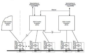
The Thales Multiple Section Axle Counter System (AzLM) is a safety-critical track occupancy detection system. The AzLM system consists of track side Detection Points (Zp30K), consisting of the Electronic Junction Box EAK30K and the rail contact Sk30K, and an Axle Counter Evaluator (ACE) which determines the occupancy status on several track sections. The Detection Points are attached to the rails at each end of a track section and generate an electric field to detect the passage of individual steel train wheels (axles).
The Detection Points maintain a count of axles passing by their location and are also able to determine the direction of travel. This information is periodically passed to the ACE which evaluates the axle counts (and direction) from all the Detection Points associated with a particular section to vitally determine the current track occupancy status. A “track free” condition is reported only if the current axle count for a section is zero; otherwise, a “track occupied” condition is reported
VOBC Subsystem
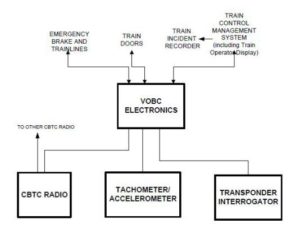
This section describes the equipment required for the S-Stock Passenger train only. The VOBC subsystem provides the interface between the CBTC system and the vehicle subsystems.
VOBC Electronics
Train Operator Display
Transponder Interrogator
CBTC Radio
Tachometers
Accelerometer
Note: The Train Operator Display is supplied by others and is driven by the Train’s TCMS.
The VOBC is in constant communication with the VCC and is primarily responsible for the control of propulsion, brakes and train doors. It interprets and executes VCC commands including maximum speed, target point, door control and braking rate.
It performs vital supervisions including overspeed, target point overshoot, and door status detection to ensure that the train is operating within its permitted envelope. The VOBC supervises train operation and automatically commands the emergency brakes (EB) to apply when safe operation cannot continue.
The VOBC’s positioning system is based on information from the transponders laid along the track and on information from tachometers mounted on the vehicle’s axles. Each transponder has a virtual loop number associated with it. Using the loop number contained in the transponder data and the information from the tachometers allows the VOBC to establish a coarse position within the guideway. Finer resolution is achieved by using tachometers to measure the distance.
Finer resolution is achieved by using tachometers to measure the distance travelled from the start of the previous transponder. The VOBC transmits data on the train’s position, velocity, travel direction, and VOBC status to the VCC.
Track Side Equipments
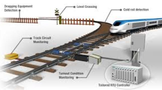
This documents defines the interfaces between CBTC system and track side equipment on the Sub Surface Railway. This document is intended to define the interfaces with existing signalling assets which are to be retained. However, in some cases , references have been made to new signalling assets to provide context. The interfaces are.
Point machines
Signals
Trainstops
Trip cock tester
Shunt signals
Compressed Air Suppliers
Point heaters
Rail Gap Indicator
Track Circuit Interrupter
Rear Cab Clear
Staff protection keys
SCC/SER/ESR Alarms.
Few Definitions
Closed track: A status applied to a track either by CBTC system reaction or by Operator Command. Controlled trains will be held at an applicable safety distance from the boundary of the closed track.
Controlled train: A train that is communicating with the wayside CBTC system and operating in a controlled mode. Communicating train operating in Restricted mode or Trip cock protected mode are not considered controlled trains.
Equipped Trains: Trains equipped with Sel Trac equipment, allowing operation under Settrac Moving Block Rules. All S-Stock and some Engineering’s trains will be fitted with Set Trac equipment. All Engineer’s trains will retain tripcocks. Tripcocks on equipped trains remain active throughout all stages of imigration.
Rail gap indicators: Lineside indicator used to inform the Train Operator that traction current has been switched off on the section ahead, so preventing trains from entering this section.
Point Machines- Electro-pneumatic Point Mechanism
Electro-pneumatic points machines are commonly used. Operation of air motor supplies the drive to move the switches. Electrical contacts within the machines are used to detect the point position. Presence of third stretcher requires a supplementary drive. Some wide to gauge points are fitted with a WL due to lack of stretcher bar.
When the point is required for the facing passenger moves, and the operating mechanism is capable of storing of energy, an additional ground lock device (WL) is used to ensure the points remain locked. This is achieved on a four foot set of points by lowering a dab into one pair of points in the drive mechanism, when the points are in the correct position. The WL must be operated first in order to release the points and allow the movement of the switch blades.
Control of the point mechanism is achieved by the operation of point lever on a ‘V’ style interlocking mechanism or a converted ‘N’ style lever frame. Point levers or computer controls electrically operate the pneumatic valves located by each point mechanism. These valves control the supply of air to the drive motor to move the points to the ‘reverse’ or ‘normal’ position. When fitted another valve supplies a separate air supply to WL.
Point Machines- Electric Point Machines
At certain locations electric point machines are also used to control the points. Electrical contracts within the point machines are used to detect the point in position. Supplementary drives are fitted to drive the point where required. Supplementary detection also be fitted for long turnouts. No ground lock is required for electrical point machine.
Control of point mechanism is achieved by the operation of point lever on an interlocking mechanism. When the detection is made the supply to the electrical motor is switched off. If the detection is not made within 7.5 seconds, the cut-off relay ensures switching off the supply to the point motor. This is to prevent the damage to the point machine. Electrical point machine also contain internal heating elements which serve to keep machine’s internal components free of ice in cold weather.
Point – Hand Worked Points
Within the depot and siding areas, many points are operated by hand, via lever at the track side which has a direct mechanical linkage to the switch blades. These points are normally detected by the signalling system.
Point – Switch Lock Points
Switch lock points are found in entrance/exit to depots. They are operated manually, via a lever and foot plunger at the track side with a direct mechanical linkage to the switch blades. The points are fitted with ground point lock device (WL) which locks the points in the normal position. This is achieved with dab engaged in a port when the point are in normal position. The main line interlocking must first release switch lock points by energising WL in order to release the points and allow blades. The main interlocking detects the switch lock points in the normal position.
Point – Loose Points
Loose points are the points which are trailing points that are un-detected/unlocked. The CBTC system cannot support this type of points as the CBTC system support points that do not have detection.
Machine types and Points Layouts
Electro-pneumatic point machines
4 foot point machine
6 foot point machine
Calmplock point machine
Chairlock point machine
Electrical point machines
Surelock point machines
Style 63 point machines.
Layouts controlled
Single-ended turnouts
Double-ended turnouts
Single slips and double slips
Four foot and six foot variants of the Surelock
Wide-to-gauge
Movable angles
Electro-hydrolic In-Bearing Clamplocks
HM 1000s and HW 2000s
Signals- Existing Signal System
Controlled signals
Automatic signals
Repeater signals
Fog repeater signals
Three-aspects Network Rail Signals
Four-aspects Network Rail Signals
Fixed red lights
Trainstop related signal controls
Signals- New Signal System
CBTC system will interface to existing signals in the following areas during system roll-out
ATC Overlay areas
Migration areas
Permanent boundaries
ATC Overlay Areas
The CBTC system will issue a Limit of Movement Authority (LMA) that will have to correspond with the signals controlled by the existing system. The proceed aspect signal status and other factors , such as the train stop lowered, points locked and detected in position, and ACB status, will be needed to advance the target point accordingly. Signals at danger including the altered red signal will be treated as an obstruction by the CBTC system.
The status of the signal aspect relay (GR), in conjunction with the train stop down status, will be fed as a vital input to the VCC via the SCS. The VCC will advance the target point. The signal control will be retained by the existing system.
Migration boundaries
At Migration boundaries entering CBTC territory a new signal capable of displaying red and ATS aspects will be installed. The signal will be directly controlled by the CBTC system via the SCS and the relay rack. The new signal head will be installed such that the existing train stop can be re-used. Two additional train stops will be installed in advance of the signal as per the applicable CBTC Signalling Principles.
Migration boundaries- leaving CBTC territory
At the migration boundary leaving CBTC territory, an existing signal will form the starting signal to TCP territory. The signal will be controlled from the existing interlocking and will be monitored by the CBTC system.
