Railway Track Switching Stations
Switching stations
1. Can be
2. Feeder stations – where electricity from Electricity Supply industry is brought and is supplied to OLE, or
3. Track Sectioning cabins or Track Sectioning Locations – which perform function of switching, sectioning, paralleling and electrical protection.
4. Are unattended, kept closed, locked and alarmed for security.
5. Switchgear is remotely controlled by supervisory control from Electrical Control Room concerned (SCADA system), and is contained within buildings or outdoor housings, or is structure mounted.
Feeder stations
1. 20 to 30 miles apart – distance between railway feeder stations determined by consideration of traffic to be handled, the performance required of electric traction units and electrical characteristics of overhead and supply systems. Not always possible to achieve optimum spacing in practice due to desirability of locating the feeder stations close to Grid substations in order to avoid long feeders and of locating feeder stations at railway junctions or intersections.
2. To keep the unbalance on the 3 phase grid system within specified limits, power for traction is tapped off the grid system across the different phases at adjacent feeder in cyclic order.
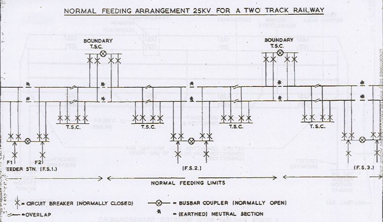
3. A Feeder station has normally two supply transformers, one will feed, say northwards and the other southwards.
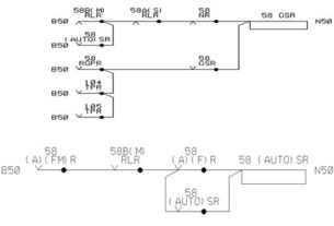
4. Catenaries are connected together on a bus bar at the feeder station and again at track sectioning cabins via circuit breakers
5. Approximately midway between feeder stations the catenaries are connected together (i.e. paralleled) at a boundary t.s.c but again two feeds (from feeder stations adjacent) are kept separated
6. At each feeder station and boundary t.s.c.s, a short length of catenary is isolated from live centenary on either side and is earthed to form Neutral section
7. Intermediate t.s.c.s are provided midway between feeder stations and the boundary t.s.c.s. This is to reduce the length of section where power block is taken for maintenance work, etc. Here again the catenaries are paralleled via circuit breakers.
8. At intermediate t.s.c.s. the contact wire is made discontinuous by terminating the contact wire from each direction (e.g. north and south) in such a way that for a short distance they run parallel to each other
Feeder and Switches
Feeders
1. A transmission line or cable in the electrical power distribution system for:
2. Bringing a supply of electricity to a Feeder station
3. Connecting a Feeder station or Track Sectioning Cabin or Track Sectioning Location to overhead line equipment
4. Cable run from feeder stations are either underground or in troughing at ground level
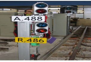
Switches
1. Feeder switch – A switch mounted on a OLE supporting structure , provided to connect a section of OLE to its feeder at a switching station
2. Section switch – A switch mounted on a OLE supporting structure , provided to connect one section or subsection of OLE to another
Jumpers
1. Cables from Feeder Stations are generally terminated in sealing ends adjacent to overhead feeding switches
2. Short jumpers are usually installed between termination of bare feeders or sealing ends of cables and switches and also between switches and the OLE.