Railway Route Release Circuits
Railway Route Release Circuits:- Approach locking
Release of Approach locking as per GK/RT0063, para 4.2.
Approach locking shall be released, after replacement of the signal to danger, either by.
- the train passing the signal is detected such that the route or track locking is effective for the route ahead of the train OR
- reasonable assurance is obtained that any approaching train has come to a stand at or before the replaced signal OR
- 3. the proof of no train is approaching the signal
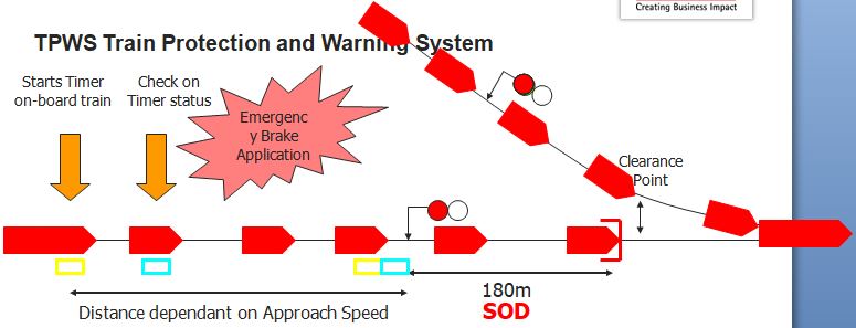
Approach/Route Locking – application
- Locking should be applied before the signal is allowed to show a proceed aspect.
- This can be either at the final stage or at the earlier interlocking stage.
Final Signal Control circuit
Locking of the route (General)
- Locking of Route is bifurcated into two parts –
- Approach Locking and
- Route Locking is popularly known as Back locking.
Definition
The locking of any route from a signal including overlap beyond the exit signal, when the driver has seen or may have seen a proceed aspect at a signal that would indicate to the driver that the former signal is displaying a proceed aspect.
1. Approach locking can be two ways.
2. Comprehensive approach locking.
3. Dead approach locking
Comprehensive approach locking is provided where necessary for operational reasons when the time-delayed release of approach locking (Dead approach locking) would be detrimental to the working of trains.
Comprehensive Approach Locking
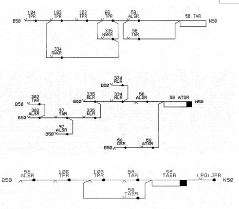
TAR (Train Approaching Relay) & ATSR (Approach Train Stick Relay) relays are used to generate comprehensive approach locking, also known as look back circuitry.
TAR
- Basically the circuit proves all the track sections in the approach of the signal in the rear are clear.
- Energizes during previous route release operation
- Remains energized till the signal is cleared again and the train is in the approach of the signal.
ATSR –
- This relay amalgamates all the TARs associated with the signals in the rear. Each signal’s ALSR in parallel with TAR should be selected by point lock relay contacts for any converging points.
- Normally de-energized.
- Energizes when signal cleared.
- Remains energized until the train is within the approach of sighting point of the last signal changing its aspect to a cautionary aspect.
- De-energizes with train is within the approach of sighting point of the last signal changing its aspect to a cautionary aspect.
- Again energizes on the release of approach locking of signal in rear
- Remains energized till the system normalized.
Both TAR & ATSR energized indicate, there is no train between this signal and the point in the rear from which comprehensive approach locking is applied.
Route Locking – ALSR
- This is achieved by the ALSR relay.
- This relay is normally in an energized position indicating the route is free.
- When a route is set this relay de-energizes indicating the route is locked.
- This, in turn, de-energizes the sectional route locking relays (USRs)
- This relay remains in the de-energized condition until conditions for the route release are satisfied.
Sequential operation of track circuits by the passage of train
- the train passing the signal is detected such that the route or track locking is effective for the route ahead of the train –
- this is achieved by sequential operation of track circuits ahead of the signal by the train. generally first & second track sections beyond the signal are chosen.
- ‘First & second track sections occupied, followed by first track section clear with second track section occupied.’
- The rest of the route is held locked by the occupation of track sections by the train.
- Each track section is released as the train clears that track section and moving ahead.
Route locking Release (Railway Route Release Circuits)
Train-In-Section Proving
TASR (Train Approach Stick Relay) energizes with the first two track sections occupied when the route is locked.
Route locking released with time
- A reasonable assurance being obtained that any approaching train has come to a stand at or before the replaced signal. This is ensured by proving the approach track occupied for a time.
- This condition provides a parallel path for ALSR to energize.
Section Route Release
- Where sectional route release facility is provided, USRs (Route Stick Relays) are provided for each track section.
- For each track section, separate USRs are provided for Down and Up directions depending upon the requirement.
- When a route is initiated NLR de-energises.
- With this all the USRs (Route Stick Relays) in the route get de-energised disabling the operation of any infrastructure in the route.
Approach locking (Railway Route Release Circuits)
- Release of approach locking can be initiated in two ways –
- Manual request from the signaler in the form of pulling of the concerned signal button.
- Train passing the signal at OFF and continuing its journey.TORR
Train Operated Route Release (TORR) –
- TORR provided at the request of Network Rail.
- TORR is essential in the case of Automatic Route Setting Systems.
- This eliminates the need for signalmen to cancel the route after each train.
- TORR releases only after the train entered the route.
Conditions for TORR to operate
- The signal controls were OFF at the time the train passed the signal.
- The signal is disengaged and prevented from re-clearing after the train movement has taken place.
- The signal is not set to work automatically.
- The signalman has not initiated the release of the route.
- Approach locking for the route has been released.
- Occupancy of two adjoining track circuits in the direction of travel followed by clearance of the first. OR
- Occupancy of three adjoining track circuits in the direction of travel followed by sequential clearance of two-track circuits. OR
- Sequential train detection employing a treadle due to some limitation of track circuits. OR
- Proof of no train approaching the signal, at the time TORR operation, is satisfied where Comprehensive Approach locking is provided.
- Where Comprehensive Approach locking is not provided, one of the following conditions shall be satisfied –
- Occupancy of two adjoining track circuits in the direction of travel followed by clearance of the first. OR
- Occupancy of three adjoining track circuits in the direction of travel followed by sequential clearance of two-track circuits. OR
- Sequential train detection employing a treadle due to some limitation of track circuits.
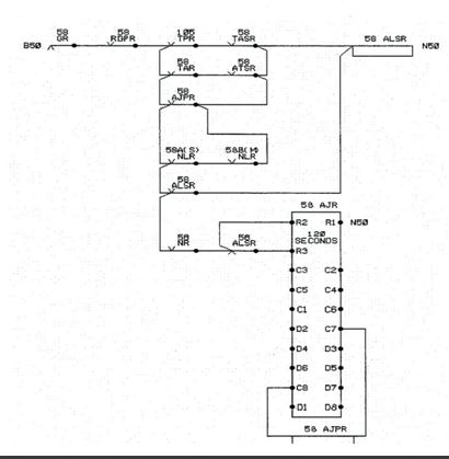
Control Table for TORR
- Control Tables specify the above three conditions as under –
- ‘Approach locking released by track circuits’ – ordinary release condition when a train has entered the route. (Standard & Alternative track sequences).
- Time-release – shown in seconds.
- ‘Approach locking applied when signal clears’ and ‘Signals ON and free of approach locking’.
Approach locking is shown in the Control table

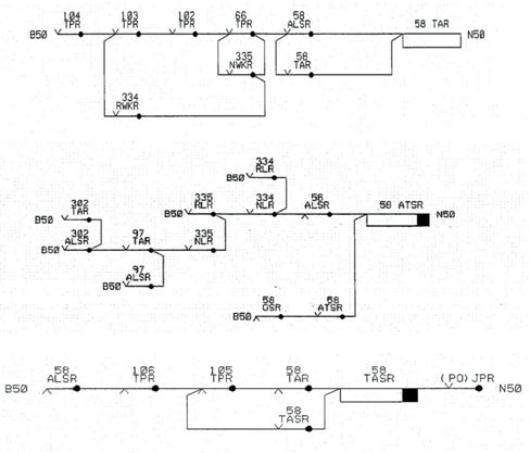
2 Red rule locking
Release of approach locking in case of 2 Reds rule –
In the case of the 2 Reds rule, the Approach locking is applied on the setting of the route. Therefore, back contacts in series of all the route RLRs for that signal are required to be proved in the un-conditional path of ALSR to ensure application of Approach locking on the setting of any of the routes.
After the passage of the train, when the signal gets replaces to ON, it should be possible to release the Approach locking. For this reason, we need to provide an additional parallel path, bypassing all the RLR back contacts by GSR back contact. Further, in the case of an auto working facility, the GSR will not de-energise after the passage of the train. So another bypass using TASR front contact needs to be provided.
There are instances when the approach locking needs to be made effective earlier than the signal controls off the stage of the interlocking. In the case of the 2 Reds rule, the Full line speed Protecting Signal (FPS) aspect controls require either a ‘route set from the junction protecting signal(JPS)’ or ‘approach release from Red’ – in addition to other controls. Since one of the conditions for clearance of the FPS is the route set from the JPS, the Approach Locking of JPS will have to be made effective on route setting itself.