AUTO CAD 2D Presentation
INTRODUCTION
The AutoCAD package is a general purpose Computer‑Aided Drafting/Designing application for computers.
There is virtually no limit to the kinds of line drawings that are prepared using AutoCAD. If a drawing can be created by hand then Auto CAD can generate it also.
Here are just a few of the applications for which Auto CAD is being used today.
All Engineering Drawings:
1. Mechanical tool and Component diagrams.
2. Civil construction plans and elevations.
3. Architectural interior and exterior diagrams.
4. Electrical wiring plans, T & D and sub‑station diagrams.
5. Electronics circuit drawings and Cartographic Mapping.
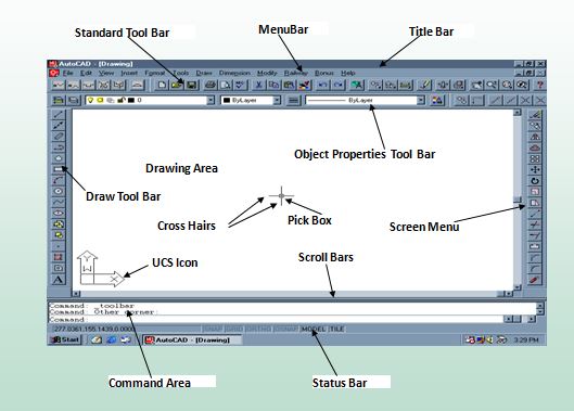
AUTOCAD WINDOW DETAILS
SHORT CUT KEYS
(A)Function Keys
F 1 Help about AutoCAD
F3 Object Snap settings
F7 Grid ON / OFF
F8 Ortho ON / OFF
F9 Snap ON / OFF
F10 Status Bar ON OFF
COMMANDS
- Move Command
Select objects Specifies which objects to move.
Base point Specifies the start point for the move.
Second point In combination with the first point, specifies a vector that indicates how far, and in what direction, the selected objects are moved.If you press Enter to accept the Use first point as displacement value, the first point is interpreted as a relative X,Y,Z displacement. For example, if you specify 2,3 for the base point and press Enter at the next prompt, the objects move 2 units in the X direction and 3 units in the Y direction from their current position.
- Trim: To trim objects, select the boundaries. Then press Enter and select the objects that you want to trim. To use all objects as boundaries, press Enter at the first Select Objects prompt.
- Copy :
Select objects: Use an object selection method and press Enter when you finish
Specify base point or [Displacement/mOde/Multiple] <Displacement>: Specify a base point or enter an option
Specify second point or [Array] <use first point as displacement>: Specify a second point or enter an option
4. Polyline:
Sets the starting point for the polyline.
If you specify a second point, you draw line segments.
If you enter a (for Arc), you draw arc segments.
- Line :
Specify first point / next pointSpecify points to draw line segments.
ContinueContinues a line from the endpoint of the most recently drawn line.
If the most recently drawn object is an arc, its endpoint defines the starting point of the line, and the line is drawn tangent to the arc.
Close Ends the last line segment at the beginning of the first line segment, which forms a closed loop of line segments. You can use Close after you have drawn a series of two or more segments.