Railway Six Foot Points
• Electro-pneumatic operation
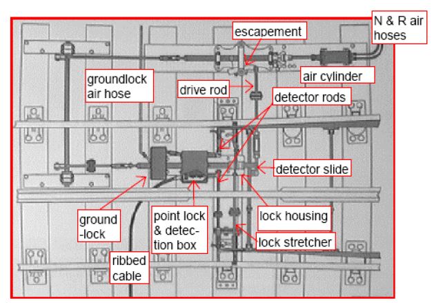
• Escapement and drive mechanism are Mounted outside the running rails
• Can be used with Bullhead rail
• Escapement, Lock and Detection as per 4 Foot Point
CHAIRLOCK POINTS
• Electro-pneumatic operation.
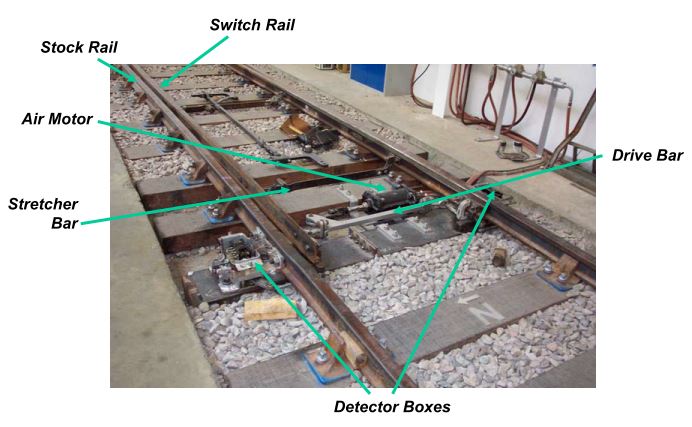
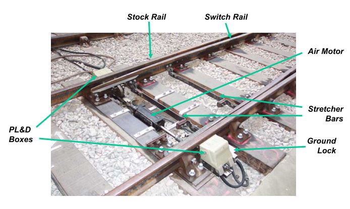
• Air motor is mounted between the running rails.
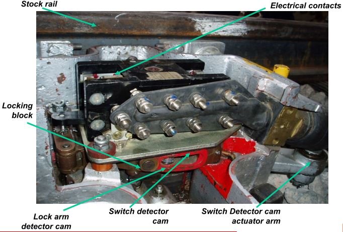
• There is no PL&D box fitted. Instead of different type of detector mechanism is used. It consists of a contact control box known as ‘circuit controller (Detector Box)’ which is fitted to the point mechanism on each switch.
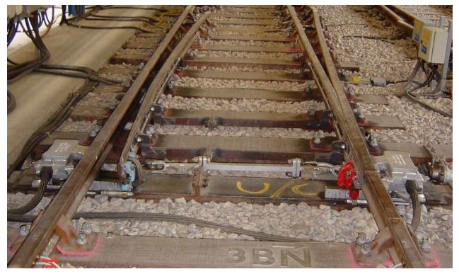
• Locking and detection mechanism is mounted side of the running rails
• Can be used on Bullhead rail only .
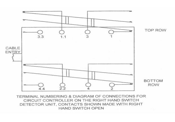
CHAIRLOCK CIRCUIT CONTROLLER
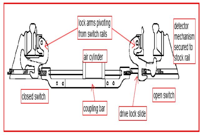
• Each point switch has an individual lock approximately in the position that would normally be occupied by a rail ‘chair’. This is equivalent to the facing point lock on the other types of points.
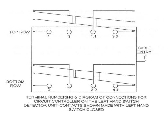
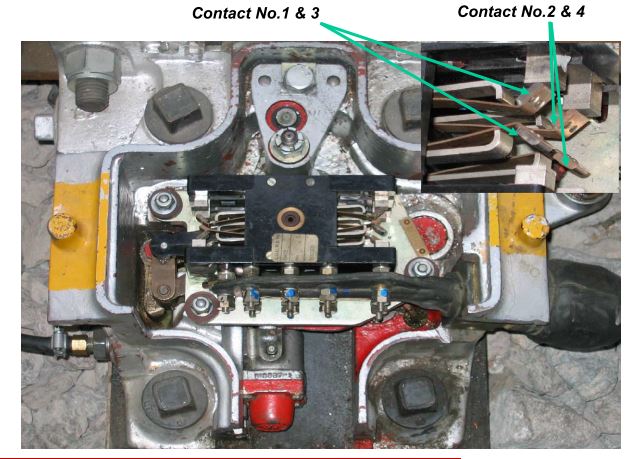
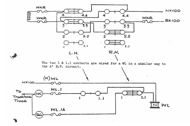
• There are four sets of contacts in each detector box, two of which are made for normal and two for reverse.
• They are numbered :- 1 & 1.1, 2 & 2.2, 3 & 3.3, 4 & 4.4.
• When a switch is closed, i.e. switch up to the stock rail, contacts 3 & 3.3 and 4 & 4.4 are made.
• When the switch is open, i.e. switch standing away from the stock rail, contacts 1 & 1.1 and 2 & 2.2 are made.
• In any contact box, contact no. 1 & 1.1 is for use in the WL control circuit or kept spare.
CHAIRLOCK CIRCUIT CONTROLLER (DET.BOX)
There are two type of layouts
1. LEFT HAND TURNOUT
• On a Left Hand Turnout, the LEFT HAND SWITCH is CLOSED with points NORMAL.
• The RIGHT HAND SWITCH is open.
2. RIGHT HAND TURNOUT
• On a Right hand turnout the RIGHT HAND SWITCH is CLOSED with points NORMAL.
• The LEFT HAND SWITCH is OPEN.
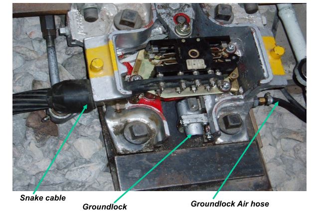
CHAIRLOCK GROUND LOCK
• Where Required, since it is a electro-pneumatic point.
• Integrated into the circuit controller.
• Needs to be detected engaged.
• Uses a dab to prevent the facing point locks from releasing.
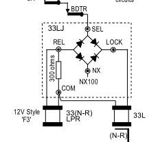
CHAIRLOCK ELECTRICAL CONNECTIONS (L.H. TURNOUT)
CLAMPLOCK POINTS
• Electro-pneumatic operation.
• It has rams driven directly by air pressure from the air main and has addition of a ground lock to LH and RH mechanism.
• Air motor between the running rails, locking and detection outside the running rails.
• Can be used on Flat Bottom rail or Bullhead rail (with adaptation).
CLAMPLOCK POINTS PL&D
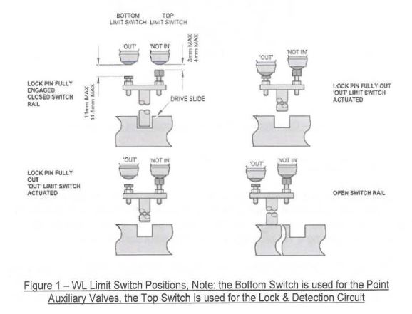
• It uses limit switches mounted in two units on each switch, one unit for switch detection and one unit for ground lock detection. These unit each contain two limit switches.
• The switch detection limit switches are designated ‘LH’ and ‘RH’.
• The right hand limit switch detects the point switch open and the left hand limit switch detects the point switch is closed.
• The ground lock detection unit limit switches are designated ‘BOTTOM’ and ‘TOP’.
• The clamplock detection units are operated by a pair of cams attached to the detector rod. As the slide moves, driven by the motor, sprung cam followers depress or release limit switches that detect if the point switch is open or closed.
CLAMPLOCK GROUND LOCK
• Required as electro-pneumatic (BR version is electro-hydraulic)
• External to the Clamp lock PL&D units.
• Works in a similar way to the 4 Foot Ground Lock (different shape, same operation). However, there is no point detection contacts for direct feed to the ground lock therefore the ground lock selection is via the point detection relay. For example, under the control of lever frame, ( R)WKR is de-energised with the track locks tracks unoccupied and lever band RC made, or ( N)WKR is de-energised with band NC made.
• Before pneumatic clamp lock points are allowed to be moved, the ground lock dab must be proved to be fully out of the locking port. This is detected by bottom limit switches which are used in the selection of the point valves.
• When the ground locks are in the locked position this is detected by ground lock top limit switches which are included in the ground lock.