CBTC Moving Block Principle
Moving Block Principle
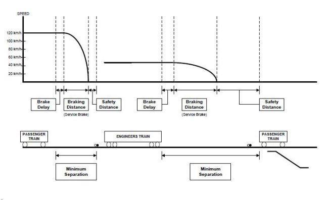
The CBTC System uses the moving block principle, in which the safes eparation behind the preceding train is dynamically calculated based on the maximum operating speeds, braking curves and locations of the trains on the alignment. Because of the high resolution of position reporting (6.25 metres), the following train may safely close up within a safe braking distance from the last verified position of the rear of a preceding train, based on the present actual speed.
In general, a significant reduction in headway relative to fixed block systems is possible since the train need not be stopped at a safe braking distance from a block that the preceding train may occupy. The primary design goal of traditional signalling systems is to maintain positive train separation through Wayside signals,
train stops and
vigilant Drivers,
that no train will enter a block occupied by another train.
In contrast, the primary design goal of a moving block system is to provide a safe system with greater capacity (throughput and inter-station run times) and reduced train separation distance through improved position resolution and Movement Authority updating rate. This is accomplished in a moving block system by using data communication with an On-Board controller (i.e. not using Wayside signal protection). A moving block system can also safely allow multiple train occupancies in the same area that would otherwise have been used for one fixed block.
Safety is paramount in the design of the CBTC system. This is achieved by maintaining a ‘Safety Distance’ between vehicles. This Safety Distance is a fixed distance between the commanded stopping point of the following train and the confirmed position of the rear of the preceding train. This distance is selected to allow for a series of worst-case conditions to exist and still ensure that safe separation is maintained.
Vital supervision of safe train separation is implemented by providing to the On-Board subsystem, information on the maximum allowable train speed and the current stopping point. The communication is updated cyclically to ensure that continuous updates are available to the train. The train, therefore, can safely operate within the envelope defined by:
the maximum commanded velocity
the confirmed stopping point
the braking curve
track grading
Routing Control
Trains are given a line (SMC lines) assignment by the SMC (System Management Center) as called for under the operating timetable. Each line assignment defines a train’s station stopping points, terminal stations and routes to be followed. Each route is composed of a sequence of point settings for a train to reach its destination.
The VCC monitors and commands point positions through the Station Controller Subsystem (SCS).
As an Automatic/Protected Manual train approaches a point, the point is reserved for the train.
Moving block operation minimises the duration of point reservations.
Where potential contentions arise they are resolved on a first come first reserve basis.
Once a point is reserved for a train, the VCC commands the SCS to position the point in the position required by the route, as well as
any associated points required for flank protection.
The SCS must receive the correct sequence of commands from the VCC before initiating a throw command to the point.
In addition, the SCS will perform a dead locking check prior to issuing the throw command.
The SCS establishes lock status only when points are detected in the commanded position and have been locked.
Limit Of Movement Authority
The CBTC System assures safe train movement by the generation and enforcement of Limit of Movement Authority (LMA) commands
and maximum commanded velocity curves. The LMA is the most restrictive of those required to assure safe train separation from the following obstructions:
last reported position of the rear of a preceding Passenger train
tracks reserved for opposing trains
tracks reserved for manual route reservations
boundary of axle counter block occupied by an engineer’s train
boundary of axle counter block occupied by NCT train
closed tracks
Primary Train Detection
Primary train detection is provided by the continuous vehicle position reporting via radio function of SelTrac. The trainborne CBTC system derives the train position using the installed transponders as per the SelTrac Signal Plan along the alignment and the On-Board tachometers/ accelerometer. The train detection design is fail safe. The VCC performs a plausibility check on the reported position before accepting the new position.
To support this primary train detection, VOBCs need to be installed on all types of trains which require primary train detection. On each train, one or two VOBCs are installed. Positioning information is derived from the combined use of tachometer signals (velocity, direction), accelerometer and transponders.
Secondary Train Detection
The secondary train detection system is based on the occupancy of axle counter blocks (ACBs). This train position detection system provides an ACB length-dependent resolution. The ACB based train position detection system provides less position accuracy than the primary one, but enables the VCC to track the locations and movements of those trains that do not have functional On-Board CBTC equipment.
SELTRAC Levels of Control

SELTRAC Levels of Control
Management Level
The overall management of the automated train control system is coordinated by the System Management Centre (SMC). The SMC performs all of the Signalling Control and supervision functions and is Safety Related.
Operations Level
Safe operation of the SelTrac system is the responsibility of the Vehicle Control Centres (VCC). The VCCs ensure safe train separation and safe train movement throughout the system.
Operations Level
Safe operation of the SelTrac system is the responsibility of the Vehicle Control Centres (VCC). The VCCs ensure safe train separation and safe train movement throughout the system.
VCC Control Area
In the general application of the CBTC System, the entire CBTC territory is divided into VCC control areas. Each VCC control area covers a section of the line and is controlled by a dedicated VCC. Where the CBTC territory is divided into several VCC control areas, the CBTC operation is seamless throughout the entire territory. The SMC Operator is free to assign Area of Control regions independent of the VCC borders.
Important Abbreviations
CBTC – Communications-Based Train Control
CENELEC – European Committee for Electrotechnical Standardisation
(Comité Européen de Normalisation Electrotechnique)
CER – Central Equipment Room
CESB – Central Emergency Stop Button
CRC – Cyclic Redundancy Check
CTF – Cable Termination Frame
DCA – Depot Commissioning Area
DCS – Data Communication System
DM – Driving Motor
DT – Data Transmission
DVTD – Dynamic Vehicle Test Device
EB – Emergency Brake
ELD – Earth Leakage Detector
EMI – Electro-Magnetic Interference
ESD – Emergency Stop Device
EU – Electronics Unit
FOTS – Fibre Optic Transmission System
GD0 – Guideway Direction 0
GD1 – Guideway Direction 1
HMI – Human Machine Interface
IOP – Input/Output Processor
IP – Internet Protocol
MR – Mobile Radio
NCT – train Non-Communicating Tracked train
NCU – train Non-Communicating Untracked train
SCC – Service Control Centre
SCR – Station Control Room
SCS – Station Controller Subsystem
SMC – System Management Centre
TIU – Transponder Interrogator Unit
TCMS – Train Control Management System
TOD – Train Operator Display
VCC – Vehicle Control Centre
VCCRP – Vehicle Control Centre Representation Processor
VDI – VCC DCS Interface
VID – Vehicle Identity
VOBC – Vehicle On-Board Controller
WRU – Wayside Radio Units
Meaning of Important Terms
Area of Control: The limits of the portion of the CBTC system that is under the control from a SMC Operator’s workstation at SCC, or from a Maintainer Workstation.
Closed Track: A status applied to a Track either by CBTC system reaction or by Operator command. When a Tracks status is “Closed”, Controlled Trains are not allowed to approach closer than the applicable Safety Distance to any portion of the Track
Communicating train: A CBTC Equipped Train that is communicating with the VCC.
Controlled train : A CBTC Equipped Train operating in Automatic or Protected Manual mode. Equipped Train :Equipped Train refers to trains that have been equipped with SelTrac equipment, which allows them to operate under SelTrac Moving Block rules.
ESD Emergency Stop Device: – The following devices are collectively denoted as Emergency Stop Devices:
- Staff Protection key switches
- Track Circuit Interrupters
NCT Train Non-Communicating Tracked Train. Any train that is not communicating with the VCC, but is being tracked by the VCC using the axle counts.
Non Communicating Train: Non-Communicating Train is a SelTrac equipped train that has stopped communicating with the VCC for any reason. From the VCC’s perspective, the term may also be used to refer to an Unequipped Train (not equipped with SelTrac equipment) since the VCC cannot differentiate between the two.
Overlay Area: CBTC Overlay Areas are Interoperable Areas where an external system controls the signals. The external control system sets routes and clears signals based on external timetable and Signaller requests. The CBTC retains authority over communicating trains, advancing train movement authority and obeying signal status.
Position: The logical resolution of the guideway. A Position is nominally 6.25 metres long.
SCS: Station Controller Subsystem, a subsystem of SelTrac for field device control and supervision.
SMC :- System Management Center, a subsystem of SelTrac for central control and supervision.
Underlay Area : CBTC Underlay Areas are interoperable areas where the existing signalling system is replaced by the CBTC system with wayside signals and trainstops being replaced. The CBTC system is able to track both CBTC and non CBTC trains to generate movement authorities based on moving and fixed block principles, respectively.
VCC: Vehicle Control Centre, a subsystem of SelTrac for Wayside control and
VOBC: Vehicle On-Board Controller, a subsystem of SelTrac for On-Board control and supervision.
CBTC System Contex Diagram
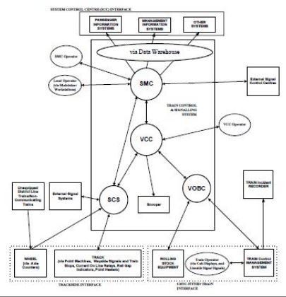
External Interfaces to CBTC
* CBTC-equipped rolling stock:
* Rolling stock not equipped with CBTC equipment
* Tripcock equipment via trainstops.
* Train Control Management System.
* Train Incident Recorder (via TCMS).
* Wheel crossing the Axle Counter Head.
Track via the:
* Train Stops
* Current On Line Relays
* Point Machines
* Point Heaters
* Traction Power System via Current on Line relays
External Signal Systems
External Signal Control Centers
Master Clock System
Timetable Generation System
SCC via the ‘Data Warehouse’ via ICS to:
* Passenger Information Systems
* Management Information Systems
Operating Staff (associated HMI):
* Mimic HMI
* SMC Operator
* VCC Operator
* Local Operator
* Train Operator via:
* TOD via TCMS
* Wayside Signals
* Rail Gap Indicators
Functionality of External Interfaces
Rolling stock equipment.
Train lines carry signals, which are either generated by the VOBC and are thus considered as VOBC output Or by train subsystems, which are monitored by the VOBC and are thus considered VOBC inputs. Vehicle Safety Critical Circuits will be connected as double wire, double break. At a minimum, emergency brake hold-off, door enable signals and door closed status will be connected as safety critical circuits (double wire, double break).
When the VOBC is in the operational state, the emergency brake is normally held-off by periodically resetting the Interval Measurement Circuit (IMC). When the IMC is not reset within the timed out period, the power to all vital outputs is disconnected and the emergency brakes hold-off signal will be disabled.
Train Control Management System
The CBTC system interfaces with the Rolling Stock Equipment for non-safety-critical data communication through the Train Control Management System. The CBTC system will transmit data to the Train Control Management System for interface to systems external to the CBTC system such as Destination Sign and Passenger Announcement Systems, Train Radio, Train Operator display and train carried Incident Recorder.
Train Operator Display:
The CBTC system will interface to the TOD, via the Train Control Management System, through a VOBC interface via the OTP card.
Wheel Crossing the Axle Counter Head
When the wheels of a train cross over an axle counter head, axle count is available to the CBTC System. This will enable the CBTC System to determine the number of axles within the block and track any Non-Communicating trains inside the CBTC System.
Point Machines
The CBTC system commands the point machine to move into position and obtains its status. The point machine conveys the status of the points to the SCS. Confirmation of the locking of points and detection of points in the correct position for safety interlocking purposes is done by the VCC.
Current Line Relays
The CBTC system will interface with the existing Current on Line Relays to determine the status of each traction power section, in order to display SMC alarms, inhibit automatic routing into de-energized sections, and illuminate Rail Gap Indicators.
Rail Gap Indicators
The CBTC system will interface with the existing RGIs. RGIs indicate to the Train Operator that the traction current has been discharged from the traction current section ahead. RGIs are controlled by the CBTC System based on the Current-on-Line Relay (also called Traction Current Detector) status for the traction section in the route ahead, the route being determined by point position if there are multiple routes beyond the RGI.
Point Heater Status
The CBTC System will interface with those existing point heater systems which are capable of remote monitoring and/or remote control, for thepurpose of controlling and monitoring them.