Railway Multi Section Digital Axle Counter
Az LM Eldyne Multi Section Digital Axle Counter
Introduction
1. The AzLM is a vital axle counter equipment for multiple track sections containing 2 out of 2 microcontrollers to count the axles, establish the track occupancy of a track section and to provide this information to the block or the interlocking equipment. It consists of Outdoor Trackside System
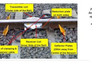
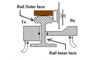
2. Double rail contact Sk30H mounted on rail consists of two coil sets Sk1 & Sk2 of Transmitter (Tx) & Receiver (Rx) installed on the same rail. The two Tx coils are fed with different frequencies (approx. 30.6 KHz and 28 KHz) which induce a voltage in Rx coils.
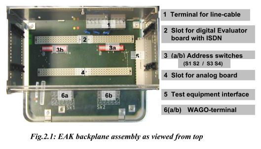
3. Track side Electronic unit EAK30H contained in the trackside housing and connected with SK30H via integral cables (available in lengths 4m, 5.5m and 8m). It consists of
Analog Card
Digital Card
Motherboard
4. Communication link between EAK and indoor equipment.
Indoor Equipment
1. Axle Counter Evaluator (ACE) installed at the station.
2. Reset Relay 1000 ohm AC immunized Q series
3. Vital Relay (QN1 8F-8B) connected externally to the Parallel Card
Fixing of track devices after replacement of rail
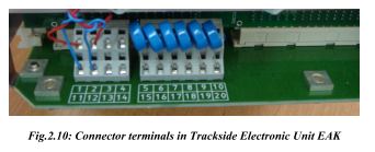
The procedure for fixing of track devices is same as that for AzLS Eldyne SSDAC. (Please refer Section I Para 1.7) Termination details of EAK
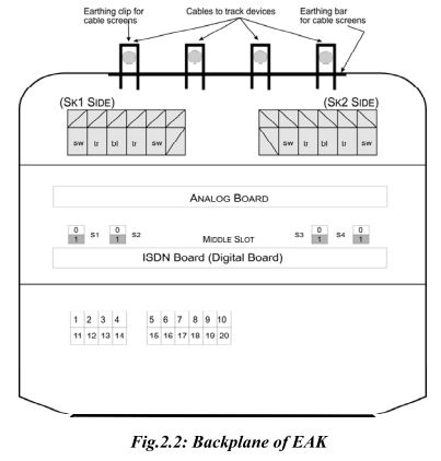
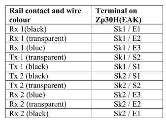
The connections of integral cables of rail contacts to the terminals of EAK are as given below:
The connections for Power Supply/Communication to the EAK are as under:
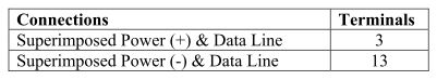
Provide a shorting link between terminal 2 & 1 and 12 & 11 if the same pair of conductors is used for superimposed data and power supply to the EAK. If separate power supply is used for installation, the communication line has to be between terminals 3 & 13 and the 60V power supply has to be connected to terminals 1 & 11.
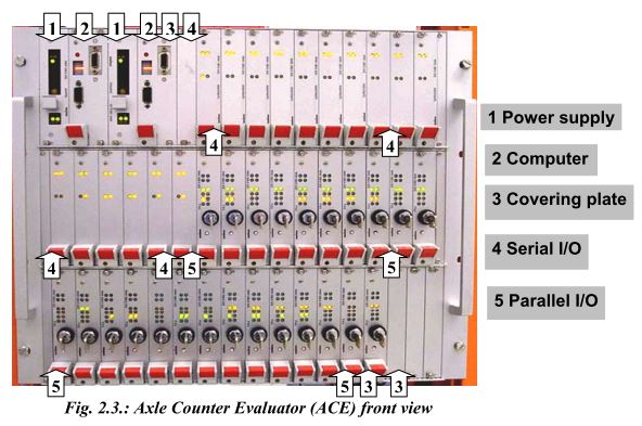
Evaluator (ACE)
Axle Counter Central Evaluator is the decision making unit for multi section digital axle counter. It has the following sub components.
CPU card
Power Supply Card
Serial Card
Parallel Card
CPU Card: Two CPU Cards are required for 2 out of 2 system. Diagnostic interfaces and alphanumeric display are available on CPU Card.
Power Supply Card: It works on 24VDC and generates 5VDC and 12VDC required for the electronic circuitry. Two Power Supply Cards are required for 2 out of 2 system.
Serial Card : receives information from detection points through ISDN communication link and provides this information to CPU Cards. One Serial Card can monitor maximum two detection points.
Parallel Card: is responsible for providing section information.
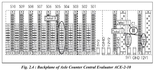
U1 & U2 are the connectors for 24VDC Supply to ACE. Polarity of the supply should be checked before connection. The slots S01 to S10 are used for I/O cards, either Serial or Parallel depending upon the site specific software.
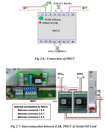
Power Data Coupling Unit (PDCU)
PDCU is the interface between outdoor equipment (Detection Point) and indoor equipment (ACE). It has a superimposing circuit for using same conductor for power and data. One PDCU is used for one detection point only. There is a 315mA fuse inside the PDCU. The power to the EAK goes through this fuse and if it is blown then there will be no power at detection point and a red LED within the PDCU will glow. PDCUs are to be installed on 35mm DIN rail. Where local power supply is used to feed the EAK, the superimposed power and data is not used. In that case, the PDCU should be used for isolation of communication line and only connector no. 4, 5 and 14, 15 are used.
Test equipment (Tool Kit) ETU001
The Test equipment ETU001 is same as that for AzLS. (Please refer Section I Para 1.6).
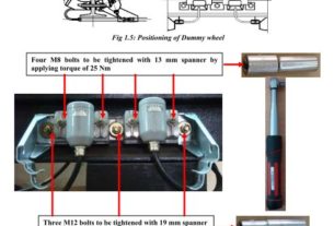
Adjustment of Rail contact Tx head with Dummy wheel and Tool Kit
The procedure for adjustment of TX head is same as that for AzLS (Please refer Section I Para 1.5).
Functions of Selector Switch in ETU 001
Functions of Selector switch in ETU 001 are same as given for AzLS (Please refer Section I Para 1.7).
Parameters to be checked for adjustment of rail contact
Outputs of DC-DC Converters, Rx Voltages MESSAB1 & MESSAB2, Reference Voltages PEAGUE1 & PEAGUE2 are checked in the same way as per the procedure given in Section
I Para 1.8. The other parameters can be checked as follows:
Axle Counter Evaluator (ACE)
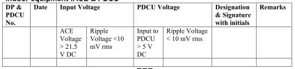
Power Supply Voltage range at ACE is 21.5 – 28.8V DC which can be measured at the connectors U1 & U2 at the backplane of the ACE. Alternatively the input voltage to the ACE can be measured at fuse terminals on CTB.
Power Data Coupling Unit
Check outgoing voltage for trackside connection box at terminal nos. 4 & 5 of PDCU
Checking Frequency of Tx heads
The frequency of the transmitter heads are to be measured by true RMS Multimeter only. For this purpose additional probe set is provided with Tool Kit ETU001. These readings can be taken at connector terminals S1 & S2 of both Sk1 & Sk2 inside EAK.
Checking of Power supply voltage to Trackside unit EAK
Recommended power supply for EAK is 54 – 120 V DC. Measure the power supply voltage fed to the track side electronic unit with the meter and the probe set directly at the power supply connector terminals 1 & 11 if separate pair of conductors is used for 60 V DC power
supply and at 3 & 13 if the communication line and 60 V DC power are superimposed in the same pair of conductors.
Adjustment procedure
Adjustment procedure is same as that for AzLS.(Please refer Section I Para 1.9)
Reset Box
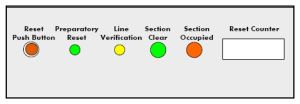
ERBM-02 is the reset box for AzLM Multi Section Digital Axle Counters. It provides the basic resetting pulse (24VDC) for 3 seconds (approximately) to ACE to reset a particular section. The front panel of the terminal consists of:
1. Push switch
2. Reset counter
3. Preparatory reset indication – GREEN LED
4. Line verification indication – YELLOW LED
5. Section Clear / Unoccupied indication – GREEN LED
6. Section Closed / Occupied indication – RED LED
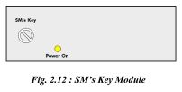
The SM‘s Key module for multisection reset panel consists of:
1. Reset Key
2. Power On LED Indication (Yellow LED)
This Reset Key acts as the common key for all the reset boxes used in a particular installation. Additionally a buzzer is provided to give audio indication that the 3-second reset pulse is on.
Resetting procedure
For resetting AzLM, the following procedure is to be adopted:
1. The authorized person inserts the KEY, turns it clockwise and then pushes. (If optional Co-operative reset key is provided this has also to be turned simultaneously by another authorized person. For this H & R are to be shorted at selection jumper J1 on PCB. If the cooperation / line verification is not required then P & R are to be shorted).
2. While KEY is in turned position the RESET PUSH BUTTON for a specific section is pressed momentarily.
3. BUZZER sounds for 3 seconds and then stops.
4. The KEY is then turned back anti-clockwise and taken out. A reset operation is only possible when section is occupied or disturbed.
Check points for maintenance
Outdoor equipment EAK
The maintenance check points for outdoor equipment are same as those for AzLS (Please refer section).
Indoor equipment ACE
1. Check the PDCUs are correctly installed on DIN rail and all connections are tight.
2. Check all fans inside the ACE cabinet are working.
3. Check the physical condition of connections in vital relays and snubbing diodes.
4. Check the backplane connections are proper and fuses are properly held.
5. Check all the cards are properly housed in the sub rack.
6. Check that the reset boxes are properly fixed on the base.
7. Check that the reset boxes are properly sealed and no termination is exposed outside.
8. Check that all earth connections are intact and making good contact and earth lead wire, nut connecting earth wires etc. are not corroded.
9. Check all spare conductors of communication 6/4 quad cable are properly earthed.
10. Check that all the indications of DP on ACE are displaying the normal function.
11. Check the DP profile in the Diagnosis of AzLM system using diagnostic software and take required action as per diagnostic software report.
12. Measure the earth resistance and paint its value on earth enclosures/nearest wall. If required take suitable steps to improve the earth resistance. It should be less than 1 Ohm.
13. Check voltage at VR, it should be more than 20 V DC.
14. Remove and replug parallel I/O cards of seldom occupied sections (clear section will indicate occupied on removal; after re-plugging, will get clear after an internal check.
Do’s & Don’ts
Apart from do’s and don’ts for outdoor equipment which are same as that given for AzLS in section, following precaution should be taken for indoor equipment:
1. Never plug in or pull out the power supply card and CPU card while the ACE is live.
2. Keep both front and back doors of ACE cabinet properly sealed and locked.
3. Ensure that ACE cabinets are earthed with 25 sq mm copper wire (or its equivalent) along with lug.
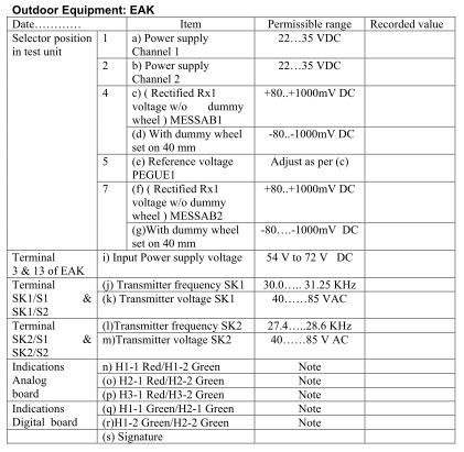
Log Sheet :- All the measurements should be recorded in the following format:
Indoor equipment – ACE & PDCU
Can i have study material on MASDAc to know more further…. As I’m working here at which station,,, we r using MASDAC.. I have no besic knowledge… Only had seen installation…
ok wil try
sir we are going to installed eledyne axle counter as a madac so provide installation manual….so we can guide or checked the contractor work
Sir
Morning
Fully class arrangement to mee