Railway Multi Section Digital Axle Counter Siemens Az S 350 U
Introduction
Az S 350 U consists of two main components:
1. Outdoor equipment
2. Indoor equipment
The outdoor equipment is the ZP 43 wheel detection equipment. The indoor equipment consists of the evaluation computer. The ZP 43 wheel detection equipment is connected to the indoor equipment via a two-core cable.
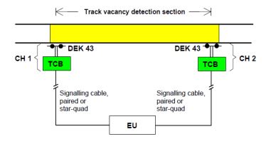
EU – Evaluation Unit
CH1/2 – Counting head
DEK 43 – Double Wheel Detector
TCB – Trackside connection box
Outdoor Equipment
ZP 43 Wheel Detection Equipment
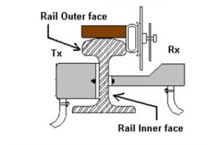
ZP 43 is the counting head which comprises a double wheel detector and a track side connection box. The track section to be monitored is called Track Vacancy Detection Section or TVDS. Counting heads are installed at the limits of a TVDS.
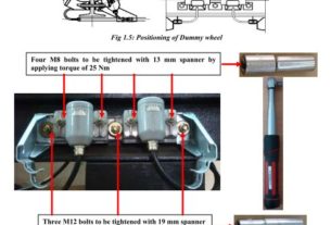
Fixing of track devices after replacement of rail Two holes of 13 mm dia. are to be drilled on rail web as per dimensions shown below:

Height X of the hole depends upon the rail profile and shall be as per table given below:
Rail profile – 60 Kg – 52 Kg – 90 lbs
Height – X 85 mm – 69 mm – 56 mm
Height of new rail – 172 mm – 156 mm – 143 mm
Permissible wear & tear – 13 mm – 8 mm – 5mm
Maintenance of AzS350U Siemens MSDAC

Indoor Equipment
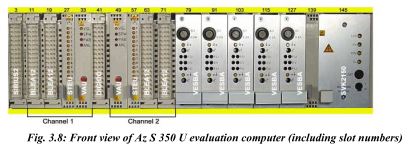
Evaluation Computer
The Evaluation Computer consists of plug-in circuit boards which are accommodated in a single-tier mounting frame with wiring back plane. Dummy boards are inserted in free slots for optional boards.
Overview of boards
SIRIUS2 board
Serial computer interface universal board
The SIRIUS2 board enables communication between the connected evaluation computers. This board is used on one channel only. On the front panel, there is a 48-pin connector for connection to all interface signals. An optional front connector with two 9-pole sub-D sockets
is used for modem connection. A service PC can be directly connected via a two-pole diagnostic socket.
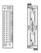
Fig.3.9: (a) Front view of SIRIUS2 board
(b) front connectors with sockets
BLEA12 board
Block input / output board with 12 relay outputs All inputs and outputs to and from the interlocking are done via the BLEA12 block input /output board. It has 12 floating relay outputs and 12 floating opto-coupler inputs. Inputs and outputs are made via a 48-pin connector on the front panel of the board. The four buttons (T1 to T4) on the front connector of the first pair of BLEA12 boards permit connection of the auxiliary axle count reset button (AzGrH).
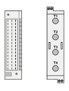
Fig. 3.10: (a) Front view of BLEA12 board (b) Front connector with buttons
STEU board
Control and diagnostic board
The STEU board buffers the signals transmitted by the counting heads. There is one STEU board per channel. The LEDs on this board display the following:
1. Normal display: display of the operating states of the four track vacancy detection sections (during operation; operating state display)
2. Statistics display (diagnostics): display of operating states for a certain counting head or track vacancy detection section (switchover / selection via AzGrH button)
3. Display after emergency shutdown: display of operating states in case of emergency shutdown
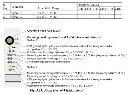
VESBA board
Amplifier, trigger and band-pass filter board
Each directly connected counting head requires one VESBA board. It provides electrical isolation between indoor and outdoor equipment (counting head). The VESBA board splits the signal frequencies f1 and f2 into two independent channels and filters, amplifies, rectifies and evaluates (trigger) the data transmitted from the counting head.
VAU board
Processing & Monitoring board
The VAU processing and monitoring board, a CPU board, constitutes the failsafe microcomputer system (SIMIS C computer core). It provides monitoring and comparator functions for synchronous dual-channel microcomputer operation.
Table B
Indication ———– Description
VGL(Yellow LED) ———– Comparator
SPW (Red LED) ———— Voltage Controller
PAB (Red LED) ———— Program-controlled shutdown
ANL (Red LED) ———— Start-up Red button System reset
DIGIDO board – Digital double-usage board
The DIGIDO digital double-usage board is used if WDE information is to be jointly used by two evaluation computers
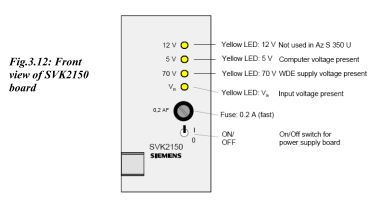
SVK2150 board – Power supply board
The SVK2150 power supply board provides 5 V for the evaluation computer and 70 V for the counting heads. The SVK2150 board transforms the interlocking voltage into controlled voltages (5 V DC for computers, 12 V DC (used for predecessor systems only) and 70 V DC for counting heads).
Power Supply
Following power supplies are required for functioning of the Axle Counter equipment:
1. 5 V DC for internal operation
2. 70 V DC for external operation of max. five counting heads
The counting heads can also be supplied with power directly from an on-site external voltage source via an additional band-pass filter board (in the ZP 43 WDE).
Reset Options
For resetting of Az S 350 U two methods are used for resetting the system:
1. Immediate axle count reset
2. Preparatory axle count reset
Immediate axle count reset
With this type of reset, the track vacancy detection section is immediately indicated as being clear after the axle count reset button (AzGrT) has been pressed, provided that no reset restriction (RR) is active. A reset restriction is active if the last axle registered by the axle counting system has been ‘counted in’. If a reset restriction is active, operation of the AzGrT button has no effect. The reset restriction can be cancelled by a relief operator action using the auxiliary axle count reset button (AzGrH). Actuation of the AzGrT button must be in conjunction with co-operation (by pressing and turning line verification key) from another agency after verifying that the track section in question is clear.
Preparatory axle count reset
With this type of reset, the track vacancy detection section in question is not immediately indicated as being clear after pressing the preparatory axle count reset button (vAzGrT). It only causes the axle count of the track vacancy detection section to be reset to ‘zero’. A
clear indication is issued only after passage of a subsequent train over the track vacancy detection section by piloting.
Technical requirements for Successful AzGrT or vAzGrT Operation
A successful reset of a track vacancy detection section (TVDS) requires that no reset restriction (RR) is effective.
Reset restriction
Depending on the configuration, the reset restriction is set according to different parameters. There might be a reset restriction, if one of the following is true:
1. Pulse detection by a counting head belonging to the TVDS:
2. There is an axle on or oscillating over the double wheel detector.
3. The power supply of the counting heads is faulty.
4. The double wheel detector or double wheel detector cable connections are faulty.
5. Counting heads of the TVDS have been traversed within the last six seconds.
6. The last test of switching capability (internal software test – SOPP) of the data channels on the VAU board has not been successful.
7. The axle last recorded by the evaluation computer in a track vacancy detection section is an axle counted in.
Adjusting ZP 43 V Wheel Detection Equipment
Tools and Test Equipment required for adjustment
1. Open-end, ring or box spanner, width across flats 13
2. Screwdriver 0.6 x 2.8 as per DIN 7437
3. Screwdriver 0.6 x 3.5 as per DIN 7437
4. Test equipment: Probe adapter board and multi-meter (Fluke-189 or equivalent) with measuring ranges.
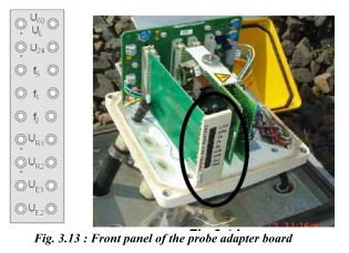
Probe Adapter Board
The probe adapter board SCN S25552-B43-D1 can be used during commissioning and maintenance for testing and adjusting work on the ZP 43 V WDE. Adjusting work (voltage and frequency measurements) can be performed using a commercially available multi-meter. Measuring sockets arranged in pairs are provided on the front panel (Refer Fig. 3.13 on page 8). The multi-meter is connected to these measuring sockets.
Multimeter Requirements
The multi-meter (Fluke-189 or equivalent) must meet the following requirements:
DC measuring range: 300 mV to 100 V
AC measuring range: 40 mV to 100 V
Frequency measuring range: 2.5 kHz to 45 kHz
Procedure for measurement/adjustment
1. Remove all stray metal parts (e.g. tools) in the vicinity of the double wheel detector.
2. Plug the test adapter board into the connector provided on the backplane.
3. Set the required AC/DC range on the multi-meter.
4. Connect the probes of multi-meter to the relevant measuring sockets provided on the front panel of test adapter board.
5. Take the measurements and adjust the parameters if required as follows:
Checking Wheel Detection Equipment Supply Voltage U60
The voltage at the measuring sockets U60 must be between 30 V DC and 72 V DC.
Checking Wheel Detection Equipment Voltage U24
The voltage at the measuring sockets U24 must be between 21.3 V DC and 22.4 V DC. This is the internal, stabilized supply voltage of the wheel detection equipment.
Setting 43 kHz Transmitter Frequency
Set the transmitter frequency using the rotary switch on the backplane to 43 kHz as precisely as possible. This frequency value is measured at the sockets FS. It must be within the tolerance range of 42.8 kHz to 43.2 kHz.
Measuring Standard Voltage UR1
The DC voltage at the sockets UR1 is measured after adjusting the signal frequencies f1 and f2 as given below. This value must be within the range of 3.45 V to 3.65 V DC.
Measuring Standard Voltage UR2
The DC voltage at the sockets UR2 is measured after adjusting the signal frequencies f1 and f2 as given below. This value must be within the range of 3.25 V to 3.45 V.
Setting Signal Frequency f1
Measure the frequency value f1 at the sockets f1. Slowly adjust the potentiometer f1 on the front of the generator board (slot 4) to the signal frequency of 3.50 kHz using a 0.6 x 2.8 mm screwdriver (tolerance range 3.47 kHz to 3.53 kHz).
Setting Signal Frequency f2
Measure the frequency value f2 at the sockets f2. Slowly adjust the potentiometer f2 on the front of the generator board (slot 4) to the signal frequency of 6.37 kHz using a 0.6 x 2.8 mm screwdriver (tolerance range 6.31 kHz to 6.43 kHz).
Checking Receiver Voltages UE1 and UE2
Measure the receiver voltage UE1 at the sockets UE1.
Measure the receiver voltage UE2 at the sockets UE2.
The voltage indicated is the voltage which is coupled into the receiver coils of the
receiver by the 43 kHz transmitter via the rail. This voltage ranges from 60 mV AC to 150 mV AC.
The receiver voltage must not be lower than 60 mV.

Do’s & Don’ts
The MOS components mounted on the circuit boards of the wheel detection equipment can be damaged by electrostatic discharge from charged persons or equipment. When handling these boards, the following rules must be observed:
1. All parts of the wheel detection equipment may be carrying an interference voltage. Therefore, always connect the measuring leads for connecting the probe adapter board and the measuring equipment to the measuring equipment first and then insert them into the measuring sockets of the probe adapter board.
2. Do not touch any metal parts of the measuring leads if they are connected to the wheel detection equipment.
3. Hold the boards only by the long sides (guide edges), front panel, locking or designation plate holder.
4. Keep the boards in their original protective packaging until they are installed in the wheel detection equipment.
5. Do not touch circuit board terminals, conductors, components or plug connectors.
6. In all adjustment work, the double wheel detector must be in the uninfluenced state (no wheels or other metal objects in the vicinity).
Adjustments and measurements at Evaluation Computer
On the front panel of each VESBA board, there are measuring sockets for fault
diagnostics as well as LEDs for displaying the state of passage and a potentiometer for adapting to different cable lengths and setting the transmission level.
Switching the Evaluation Computer On and Off
Switching ON
Restarting an evaluation computer means switching on all computer channels either for the first time or after a fault.
1. Set the switches of the power supply boards to “I”.
2. Simultaneously press the red buttons (system reset) on both VAU boards of both computer channels for approx. 1 sec., the LED “ANL” must light up on both VAU boards for approx. 3 sec.
2. After the LED “ANL” on the VAU boards has gone off, the LED “VGL” will light up.
3. During computer start-up, all LEDs 0 to 11 on the STEU boards light up for max. 10 sec. As soon as the LEDs change to normal display, the evaluation computer is operable (LED 0 shows steady light).
4. When an evaluation computer is restarted, it is guaranteed that all track vacancy detection sections are first indicated as being “occupied” and displayed accordingly. In accordance with the configured reset type (AzGrT or vAzGrT) and the railway regulations the authorised person must then perform the axle count reset. No train movement should be carried out during this procedure.
Switching OFF
The evaluation computer may only be switched off in consultation with the SM/ authorised person. For switching OFF a computer for corrective maintenance or long-term shutdown purposes:
1. Set the switch of the power supply board to “0”.
2. In case of long-term computer shutdown, the supply voltage must be switched off, do not exceed the admissible out-of-service period of. 5.5 months (only if supply voltage is switched off immediately after channel failure).
3. If these times are exceeded, special safety measures must be performed. The evaluation computer may only be put into operation again by Siemens specialist staff.
Replacing Boards
Only remove or insert boards and front connectors when the computer is in the de-energized state. Removing and inserting boards in the energized state may damage or destroy boards or computer.
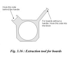
Removing Boards
To remove boards, proceed as follows: Loosen the knurled screws at the upper and lower locking bars of the mounting frame (if present).
Remove both locking bars. Loosen front connectors (if present). If the board is supplied with a handle, pull at the handle to remove the board. Remove boards without a handle using the extraction tool. Pull out the board completely.
Inserting Boards
To insert boards, proceed as follows: Slightly press up the upper locking bar and insert the board into the mounting frame according to the location diagram. Plug in front connectors (if present) previously prepared and tighten them. Tighten the knurled screws of the locking bars. The VAU board must always be replaced in pairs
Kindly let me know how much price for supply , installation and testing commisioning of one MSDAC set in railways. And let me know how many MSDAC ‘s are need to install in 3 lines single (New BG line) yard.
Hope u r team reply me soon.
Hello Sir
Plz. see below link if you required a Digital Multimeter for maintenance of Axel counter.
https://rishabh.co.in/product/305/rishabh-6012601360156016-bluetooth-multimeter
If FS was not adjusted manually what can I do
I changed mother board card bus FS value not changed
Hello Sir
Plz. see below link if you required a Digital Multimeter for maintenance of Axel counter.
https://rishabh.co.in/product/305/rishabh-6012601360156016-bluetooth-multimeter
Hello Sir
Click on link below for Digital Multimeter suitable for maintenance of Axel counter.
https://rishabh.co.in/product/305/rishabh-6012601360156016-bluetooth-multimeter
Sir plz tell me, how to check sencor frequency ? In TX and Rx , and whai is the ranges in tx and rx 🙏
If any rail cut or damage occurred…how does MSDAC work
If any rail cut or damage…how does MSDAC work
Is it fails due to movement of trolley ( insulated )
How can we pass the counters with heavily loaded material trolley