Railway Signalling Speed Restrictions – Presentation
DEFINITIONS
- PERMISSIBLE SPEED – The authorized maximum speed over a section of line.
- TEMPORARY SPEED RESTRICTION – A speed, less than the permissible speed, applied for a pre-planned period not normally exceeding 6 months.
- EMERGENCY SPEED RESTRICTION – A speed restriction not shown in the Weekly operating Notice (WON), or which is more restrictive than shown, or which applies at a time other than that shown in the WON.
- WEEKLY OPERATING NOTICE– The official printed notice advising drivers of alterations to permissible speeds.
AUTHORISATION
- The value of all permissible speed and temporary speed restrictions shall be authorized by the Infrastructure Controller.
- On lines which are used in both directions, it is possible to authorize different speeds for each direction of travel.
CLARITY OF SIGNING
Signing of speeds and restrictions should give clear and unambiguous information to the driver.
All boards and indicators should generally be placed to the left of the track. In cases where it is not possible to do so they should be placed on the right hand side after due verification that they would not cause any confusion to the driver and/or be misread as applying to another line.
Positioning should be considered in relation to all other signs/indicators so that the information conveyed to the driver is clear.
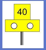
Permissible speed Indicator
* Speed indicators for standard speeds shall comprise a single indicator displaying the speed.
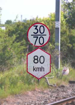
Differential speeds
Differential (Speed Restriction) : A speed restriction having two varying restrictions, each of which is applicable to different types of train.
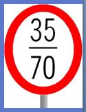
Speed indicators for standard differential speeds shall comprise a single indicator displaying the lower speed above the higher.

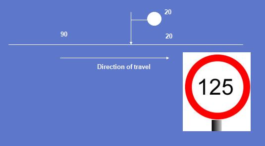
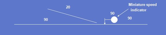
Permissible speed Indicator- Converging junction.
* Where permissible speed beyond a junction is the same as that on the higher speed route through the junction and is higher than the speed on the converging route, a speed indicator is not required for trains approaching from the converging route.
* It is permissible to provide a miniature speed indicator as a repeat sign immediately after a converging junction where the permissible speed beyond the junction is higher than that on the converging route.
Permissible speed Indicator- Diverging junction :
* A speed indicator with an arrow indicating the direction of the diverging route shall be provided immediately before any diverging junction over which there is a reduction in speed.
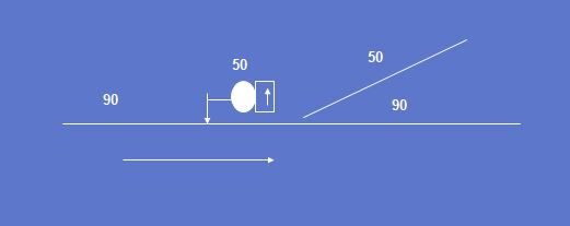
* Where a lower permissible speed applies equally to both the routes a single permissible speed indicator shall be provided without directional arrows.
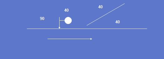
* Where differential speeds commence for each route at a diverging junction, two indicators shall be positioned side by side. Arrows shall be provided to indicate any divergence.

Temporary Speed Restrictions – Procedures
* The infrastructure controller shall devise and apply procedures for the administration, implementation, alteration and withdrawal of temporary speed restrictions. The procedures shall be documented and responsibilities shall be clearly defined.
* Any temporary alterations required are fully documented and approved by the infrastructure controller, and the implementation of the alterations is co-ordinated with the introduction and withdrawal of the temporary speed restriction.
* Equipment is provided and removed at the correct time, is correctly positioned.
* Implementation of temporary speed restriction shall only commence after notification to the drivers has been given through WON. Where this is not possible ,it shall be treated as a emergency speed restriction.
* Temporary speed restrictions are generally for less than six months period.
Emergency Speed Restriction
The infrastructure controller shall have a documented procedure for advising emergency speed restrictions to drivers.
PERMANENT SPEED RESTRICTIONS
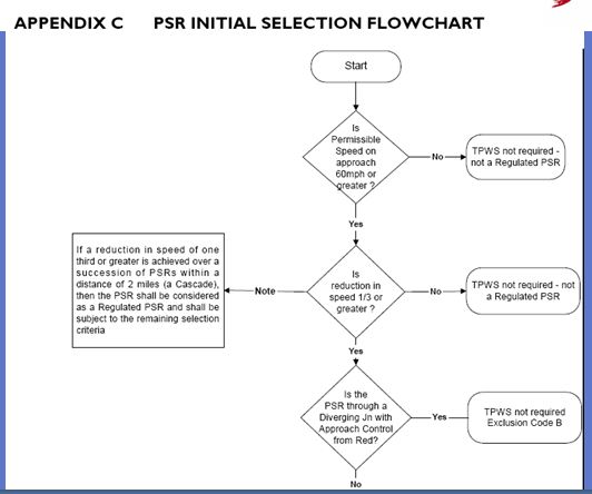
TPWS will be provided to protect Permanent Speed Restrictions on passenger lines where the approach speed is 60mph or more, and the speed reduction is one third or more.
PSR INITIAL SELECTION
Initial selection for fitment of TPWS on a PSR is done as per flowchart in Appendix C of RT/E/S/10137 Issue 3.
Additionally TSRs that are planned to be in place for greater than six months but not exceeding 12months shall be considered for fitment subject to risk assessment in accordance with flowcharts in Appendices D & E of RT/E/S/10137 Issue 3.
PSRS REQUIRING FITMENT
PSRS REQUIRING FITMENT:
A Plain Line on curve
D Approach to converging junction
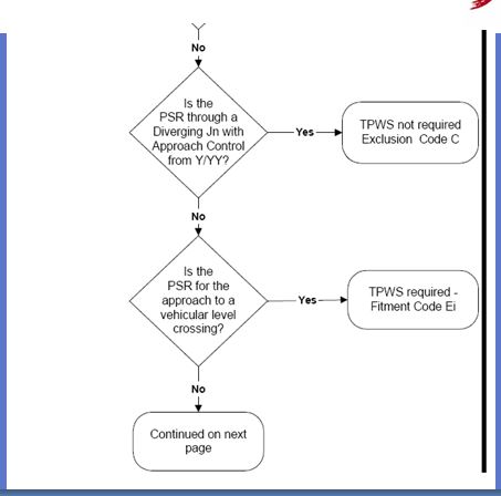
Ei Approach to vehicular level crossing
G Approach to Terminal Platforms
I Provided for Reduced Signal Spacing / Overlap
Jii Provided for Asset protection safety
Ni Diverging Junction – Signal not Approach Released
Niii Diverging Junction with splitting distant (No Approach Control Signalling)
PSRS NOT REQUIRING FITMENT – EXCLUSION CODES
B Diverging Junction – Approach Released from Red
C Diverging Junction – Approach Released from Y/YY
Eii Approach to footpath or bridleway crossing
EXI No protection provided to passenger trains due to freight train timer issue
F No longer used (was PSRs on RETB Lines)
H Approach to Emergency crossovers
Ji Provided for Asset Protection (Commercial)
K Provided for Gauging or Aerodynamic Purposes
Mi Attainable Speed less than 60MPH
Mii Attainable speed less than agreed Excessive Speed
Nii Diverging Junction indicated by Flashing Aspects
Q Trackworker protection
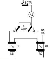
PERMANENT SPEED RESTRICTIONS
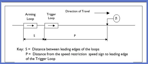
Figure below shows the general positioning layout of the OSS on the approach to a speed restriction.
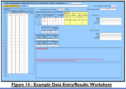
Following the initial selection, final selection shall be carried out in accordance with Appendix E of RT/E/S/10137 Issue 3, using Excel spread sheet TI-14_6.xls
Due to the complexity of determining loop positions and the iterative process of determining fitment criteria based on issues involving train performance, these calculations shall only be made by using the design tool developed and validated specifically for this purpose by AEA Technology Rail – “TPWS at Speed Restrictions: Loop Positioning Spreadsheet – June 2003 Issue 6.0” (TI-014_6.xls). The input page for general application is shown in the next slide.

Pl give details of standerd of interlocking and highest Speed permissible over it