Railway Signalling Equipment Treadle Presentation
What is Treadle?
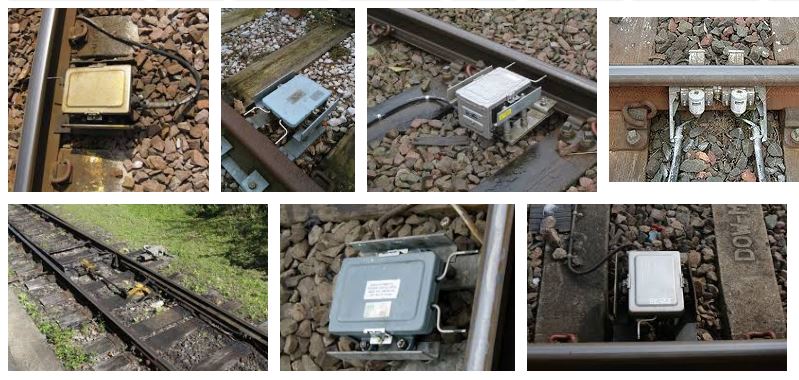
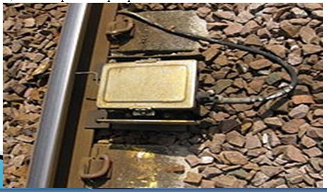
A treadle is a mechanical or electrical device that detects that a train axle has passed a particular location. They are used where a track circuit requires re-inforcing with additional information about a train’s location, such as around an automatic level crossing, or in an annunciator circuit, that sounds a warning a train has passed an exact point. The important difference between a treadle and a track circuit is that while a track circuit detects a train over a distance as long as several kilometres, a treadle provides pin-point detection.
Types of Treadle
Single Arm treadle:
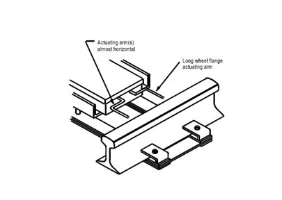
Treadles are available in two styles, 59 and 69. They are readily identified by the profile of the actuating arm. See figures 1 and 2.
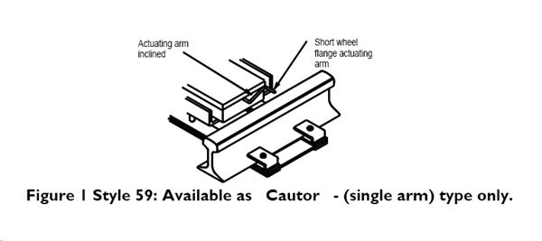
Figure 2 Style 69: Available as “Forfex” – (double arm)
The “Cautor” (single arm) treadle may be of either style 59 or 69.
The “Forfex” (double arm) treadle is only available as a style 69. There are different versions of the “Forfex” treadle according to the direction of travel that is to be detected.
Directional Treadles
“Forfex” type double arm treadles are available in different configurations: bi-directional (standard model) or uni-directional.
The bi-directional model has two independent reversing contacts, one on each armcorresponding to the two directions of travel. This is the standard model and will detect trainsrunning in either direction.
When the two independent reversing contacts are mounted on one arm the treadle becomesuni-directional. The treadle will only detect trains running in one direction, i.e. from A to B or from B to A.
The direction of detected travel cannot be changed on site. Treadles of each configuration (A to B and B to A) will be required for opposite directions of travel.
The direction of detected travel will be indicated by either a red painted arrow or a red oblong metal label. One end of the metal label will be extended to form a point.On the bi-directional model the label will be pointed at both ends. The painted arrow will have a head at each end. The arrow or label will be found on the exterior of the terminal access cover.
“Cautor” single arm type treadles are bi-directional and detect trains running in either direction
Installation of Treadles
It is recommended that treadles are not installed within 3 metres of a rail joint. This is to minimise vibration, which can cause fixings to loosen, cables or wires to chafe or break.
At existing installations where loosening of fixings or damage to cables and wires is a problem, the proximity of a rail joint may be the cause.
If there is a rail joint within 3 metres, do not move the treadle as the correct operation of equipment could be affected. Advise your manager, so that the necessary arrangements can be made for the design to be checked to ensure continued correct and safe operation.
Actuating Arm – Setting The Position
The height is measured vertically between the portion of the actuating arm that makes contact with the wheel flange and the rail level. The rail level is determined by stretching the bob weighted string over the top of the two rails of the relevant track.
For a type 59 Treadle – the top of the arm should be 11 mm (±1 mm) below rail level.
For a type 69 Treadle – the top of the arm should be 16 mm (±1 mm) below rail level.
For both types – the end of the arms should be 10 mm (±2 mm) from the running edge of the rail.
Treadle Renewal
Treadles should be renewed before they wear to the point that there is a risk of failure. The rate of wear is related to line speed, traffic density, vibration and arm return times. The arrangements for determining the frequency of change will be as laid down in local instructions.
If the wheel flange contact arm shows wear of 50% (3.5 mm) or more of its diameter it should be reported to the manager and arrangements made to change the treadle. The slot in the Treadle Gauge should be used to perform this check.
Timing Adjustment – General
The manufacturer recommends that the time taken for the depressed arm to rise fully is 8 seconds (at 20oC). At this setting the timing can be expected to remain constant over a wide temperature range.
If the time setting is reduced the wear on the treadle will be increased as the treadle actuating arm will be struck more frequently by the wheel flanges.
Timing Adjustment – “Cautor” Type (Single Arm)
Depress the actuating arm fully, ensuring the bottom contacts make, releasing of arm should take between 6 to 8 seconds to return to its normal position. If adjustment is required the operating time can be altered by using the timing adjustment screw. The timing adjustment screw must not be removed from the dash pot.
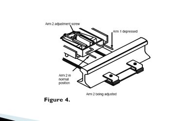
Timing Adjustment – “Forfex”
Depress fully and hold down actuating arm 1. Depress fully actuating arm 2. Release arm 2 and time the delay for it to return to its normal position. See figure 4.
The delay is the time for the arm to move between its bottom and top stops and must be determined visually. The delay should be between 6 to 10 seconds.
If adjustment is required the operating time can be altered by using the timing adjustment screw. Take care to adjust the correct screw i.e. the one furthest from the arm being adjusted.
Caution: Where adjustment of the timing is required the adjusting screw should be turned carefully and without undue force. Timing adjustment screws must not be removed from the dashpot nor tightened fully home.
Repeat the procedure for the other arm, depressing and holding arm 2 and then timing arm 1.
Depress both arms fully and release simultaneously. The time between simultaneously releasing the arms and the point at which the control rod falls to the bottom of the V must also be within 6 to 10 seconds, regardless of the order in which the arms are lowered. If either of the values is lower (or higher) than the required value, turn the adjusting screw of the last arm lowered in (or out) as required (e.g. arm 2 adjustment screw for direction 1 to 2). If both values are lower (or higher) adjust both screws.
pls send me using treadle contacts.
Assume 1 Treadle is cut-in to the track circuit and the other one is not.