ALLOCATION OF FREQUENCIES| RAILWAY AUDIO FREQUENCY TRACK CIRCUITS |PRINCIPLES OF THE OPERATION|QUADRUPLE LINES|TRANSMITTER -Tx|RECEIVER -Rx|TUNING UNITS|CENTER FED AFTC| TRACK CIRCUIT LENGTHS|TRACK CIRCUIT LENGTHS|PHYSICAL REQUIREMENTS|WIRING DIAGRAM| CONFIGURATIONS OF AFTC
Railway Audio Frequency Track Circuits
- It’s a type of AC track circuit in which audio frequency signals are used instead of pure AC or DC signals.
- Its generally a joint less track circuit, extremity of the tracks are defined by tuned units but can also be used with IRJs.
- it is least prune to interference and hence can be used in ac, dc, and non electrified areas.
- It has built in time delay and hence do not need slow to pick up track repeater.
- It is a double rail track circuit and must not be connected in single rail mode. Hence generally not suitable for S&C area.
PRINCIPLES OF THE OPERATION
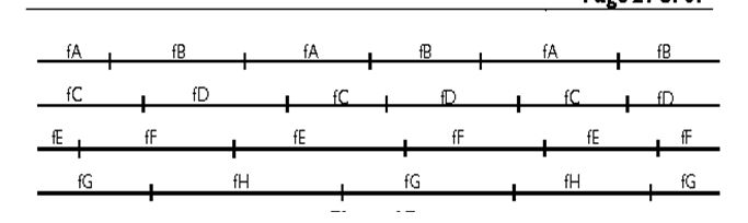
ALLOCATION OF FREQUENCIES

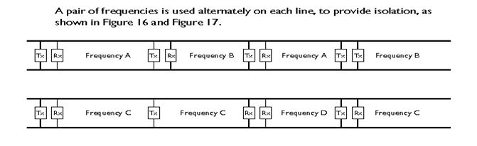
Quadruple lines
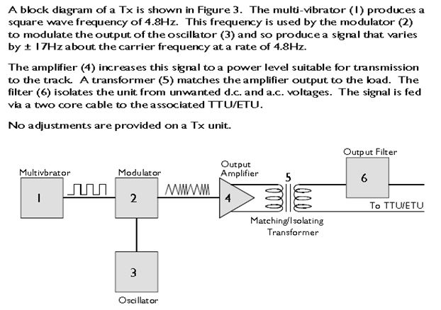
TRANSMITTER -Tx
RECEIVER -Rx
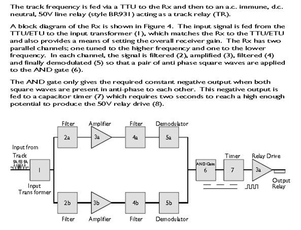
TUNING UNITS
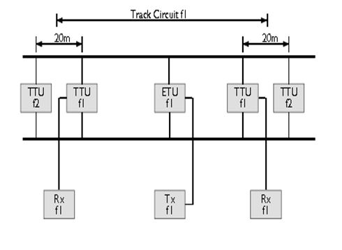
- A Tuned capacitor/inductor circuit is used to provide correct termination defining the end of a TI.21 Track circuit. Tuning units are two types, ETU and TTU
- ETU – Use of ETU at an IRJ enables the train shunt to be effective up to the IRJ. In this case ETU can be used either with Tx or Rx.
- Max distance permitted between IRJ and ETU rail connection shall not exceed 1m.
- ETU also enables the Tx to feed two receiver units of the same frequency.
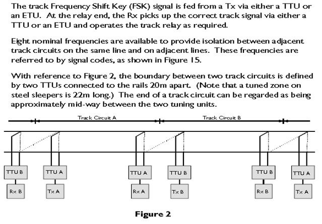
- TTU – Where two joint less track circuits abut a TTU from each track circuit is connected to the rails 20m apart to form a tuned zone.
- The shunt zone of each track circuit extends beyond mid point between TTUs.
- Each TTU provides specified load for the correct frequency and acts as a short circuit to other frequencies of the adjacent tracks
- Each TTU is sensitive to a specific frequency and blocks other permitted track circuit frequency
- Separate TTU are to be used with different frequency track circuit
- If the next section of the line is non track circuited then a tuned zone shall be followed by A IRJ at 18.5m.
CONFIGURATIONS OF AFTC
- AFTC comes in two configuration – End fed and center fed
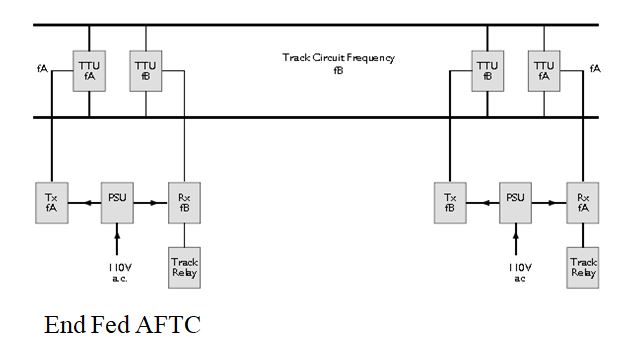
Center Fed AFTC
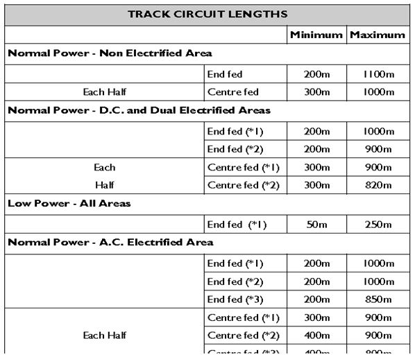
TRACK CIRCUIT LENGTHS
- The limits of the Track circuits shall be defined by IRJs in both the rails or by tuned zones.
- As TI.21 is used in double rail configurations, impedance bonds shall be used for cross bonding and in plain line shall be implemented with series bonding on both rails.
- Min length of track circuit is based on two factors:
No Rx is to be positioned less than 200m from any normal power TX of same frequency
No Rx is to be positioned less than 50m from low power Tx of same frequency.
- The min length restricted in End fed is required to false feeding of a RX by a TX of the same frequency, which is being used by another track circuit on the same line.
- Low fed is to be used only in End Fed mode and it must be ensured that no normal TX is within 200m of Rx of the same frequency
- Length shall also be imposed in locations susceptible to dampness such as tunnels
- In LC gate area, only normal power AFTC is recommended
- There are lot of restrictions for use of TI.21 and other frequency based TCs such as reed/Aster and axle counter
IMPEDANCE BONDS
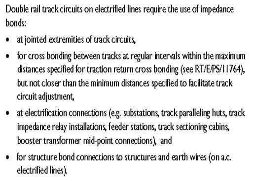
In TI.21 area structure bonds cannot be connected to rail as rail can not be earthed.
PHYSICAL REQUIREMENTS
Tail Cable – max loop resistance and length
- Tx -0.5 Ohms and max length with 2.5 sq mm cable is 30m
- Rx – 6.0 ohms and max length with 2.5 sq mm cable is 365m
- Track cable 70and 35 sq mm cables
- Power supply units – BR 929 24V Current rating 4.4A and can feed any number of Rx & Tx combination within max limit (Tx power – 2.2A and RX power is 0.5A)
- Track relay – 50V BR931 style relay and should be in same loc case as Rx
WIRING DIAGRAM


Please provide more and latest information on railway signalling like electronic interlocking, route relay interlocking and much more .please provide downloading option.
ok thanks
Please provide me UFSBI double line diagram