Railway Use of Axle Counters Fouling Point Clearance point
Railway Use of Axle Counters Fouling Point Clearance point:- The Design requirements for train detection systems includes the following:
- Interface with authorized rail vehicles (positioning of IRJs, minimum track circuit lengths, which may be dependent on permissible speed, and interlocking measures to mitigate against any deficiencies)
- Interface with the permanent way (IRJs, standard rail bonding with pre-drilling requirements, and S&C bonding configuration)
- Interface with electric traction infrastructure (single or double rail configuration and impedance bond position)
- Interface with the interlocking system (operating times and measures to mitigate against the false release of interlocking when there is a significant risk)
- The requirement for secure power supplies and/or battery back up
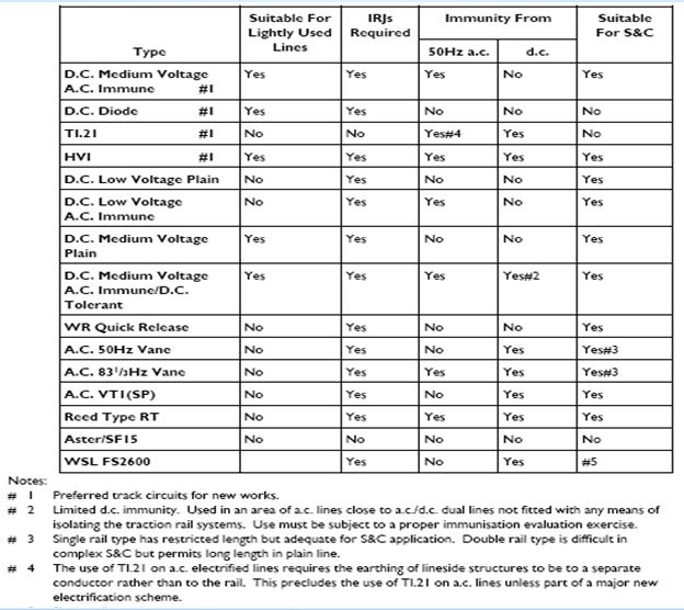
Design Consideration for choice of train detection
- The need to detect vehicles on poor rail surfaces.
- The need or otherwise to avoid insulated rail joints.
- The need for immunity to AC and/or DC traction interference.
- The need to achieve maximum reliability at an economic cost.
- The need to track circuits through complex S&C.
- The type of sleepers, where ballast resistance is critical.
- The length of a train may need to be measured.
Different types of train detection systems Axle Counters Fouling Point Clearance point
1. Track circuits
2. Axle counters
3. Other types of wheel detector, e.g, treadle, electromagnetic proximity device(used for HABD)
4. Supplementary systems, e.g, track circuit assistor interference detector(TCAID), track circuit interrupter.
Key Attributes & Limitation of Track circuits
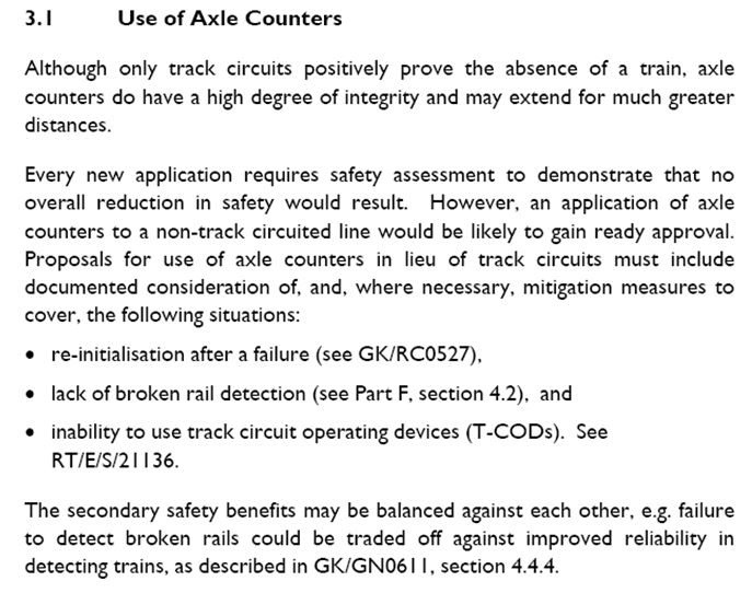
Use of Axle Counters – Axle Counters Fouling Point Clearance point
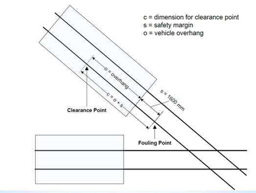
Fouling Point
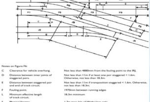
1. This is a position a short distance away from the point of running line divergence (crossing nose). Should any part of a vehicle on one track be between the crossing nose and the fouling point, it will make physical contact with any vehicles passing on the other route.
2. The fouling point occurs where the distance between the running edges of the two rails is 1970mm, measured at right angles from the diverging line.
3. In the case where tracks become parallel with a running edge separation of less than 1970mm, the fouling point occurs where the tracks first become parallel.
Clearance point
Determination of clearance point:- Figure shows the relationship between the clearance point and the fouling point. In particular, it depicts that the clearance point is determined by adding the maximum vehicle end overhang* allowed for a line and the allowance of 1600 mm. The allowance includes the rollback allowance of 1300 mm, which is provided to accommodate potential rollback after the train has come to a stand.
maximum vehicle end overhang :
- a) 5000 mm for new high-speed lines.
- b) 4200 mm for other lines.
Determination of clearance point