Railway Point Operation Of The Ground Lock (WL)
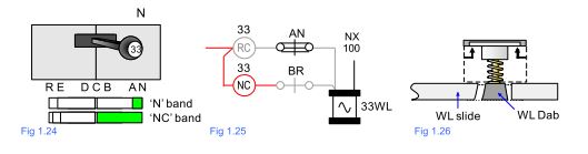
Railway Point Operation Of The Ground Lock (WL) :- With the controlling lever (Fig 1.24) and the points laying Normal, the feed from the W fuse passes over the TR contact (not shown) and the NC band to the BR contact (Fig 1.25). As the points are laying Normal, the BR contact will be broken and therefore the feed cannot reach the WL which will be de-energised and engaged in the port. (Fig 1.26)
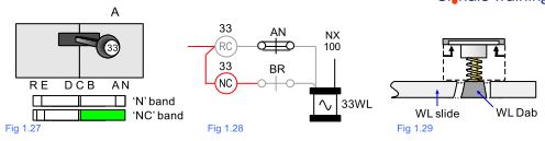
As the lever moves towards the Reverse position the N lever band breaks (Fig 1.27) and the NW point auxiliary valve de-energises (the ‘D’ valve design ensures that air is still maintained to the point motor).
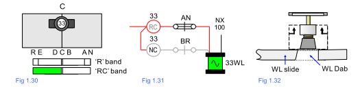
At the C position (Fig 1.30), the NC contact breaks, but as the WL is already down this has no effect. (It should be noted that in theory both the NC and RC contacts are made at the C position. This does not affect the circuit operation and in actuality the contacts are adjusted by the Locking Fitter so that they are both broken briefly at this position).
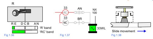
When the RC contact makes (Fig 1.31), a feed passes to the AN contact which at this moment is made as the points are still laying fully Normal. The WL circuit uses an RC band (rather than an R band) to energise the WL a brief moment before the RW to ensure that it is fully out of the port before the slide starts to move (Fig 1.32).
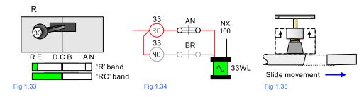
When the lever reaches the R position (Fig 1.33) the RW valve energises and the points start to move (1.35).
After approximately 5/8″ (16 mm) of slide movement the AN contact in the P&LD box breaks causing the WL valve to de-energise (Fig 1.37). At this point the WL dab will drop on to the slide (Fig 1.38). It should be noted that the WL dab will not drop back in to the port as the action of the slide moving away has withdrawn the port from underneath the dab position.
The slide eventually completes its travel and the WL drops into the destination port.
Once the dab is fully in the port it needs to be proved in position before a train is allowed to travel over the points. A WL proving contact built in to the unit makes when the dab is fully in to the port and breaks when the dab is resting on the slide or fully retracted.
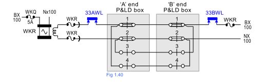
This contact is placed between the feed fuse and the P&LD contact in the WKR circuit as shown below in blue in Fig 1.39.
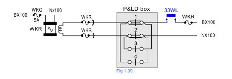
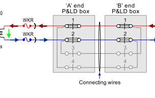
On double ended point layouts the WL contacts are inserted into the circuit in the positions shown below as required.