Railway Chairlock Circuit Controller Box
Chairlock Circuit Controller Box :- As already discussed in Unit 6, the circuit controller boxes are handed and must be fitted to their correct respective Chairlock units. Here we will look at the physical contact numbering of the circuit controller boxes and their positional relationship to the point switches.
Figures 5.15 and 5.16 show left-hand and right-hand circuit controller boxes and their terminal numbering. Both boxes are viewed from the front. The numbering of the contacts is also moulded onto the end of the cable snake that is connected to the circuit controller boxes.

Figs 5.17 and 5.18 show the left and right hand circuit controller boxes respectively as viewed from above while standing at the tips of the switches. The four letters A, B, C and D correspond with the terminal numbering shown in Figs 5.15 and 5.16. There are two rows of contacts, the top and bottom rows.
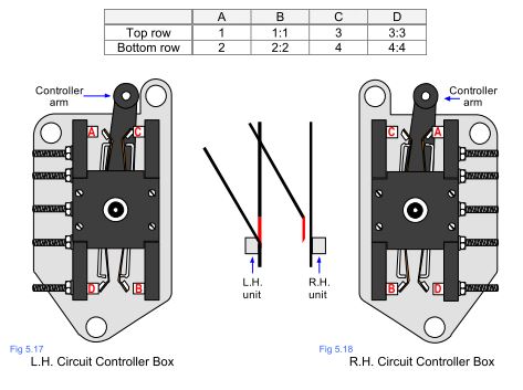
There is a positional relationship between the rail switches and the circuit controller box arms. The controller arms align with the route that would be taken by a train travelling over the points.
Figures 5.17 and 5.18 show the points in the Normal position with the arms ‘pointing’ to the right. As the left-hand switch is closed a train would be directed towards the right most route.
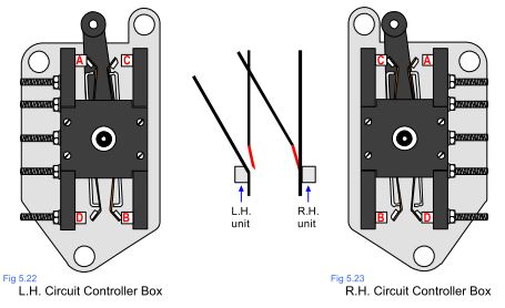
Figures 5.22 and 5.23 show the points in the Reverse position with the arms ‘pointing’ to the left. As the right-hand switch is closed a train would be directed towards the left most route.