Railway Point Circuit Introduction To re-cap The Controlling Lever The Point Control circuit The Detection circuit The WL Control circuit The Lever Lock circuit The Indication circuit Point Detection The P&LD Box The Three Position WKR
Railway Point Circuit
Railway Point Circuit Introduction
The majority of points used on the London Underground are pneumatically operated, the most common types being Four Foots, Chair locks and Clamp locks. On the Central Line, electrically driven points such as M63’s and HW1000’s are used as there is no compressed air main supply available. In some areas, Four Foot and Chair lock points have had their pneumatic motors replaced by electro-hydraulic units. The control circuits vary slightly from air worked points; however, the principles remain pretty much the same.
This Unit will deal with all the circuits associated with air worked Four Foot, Chairlock and Clamplock points controlled from a ‘V’ style lever frame. The circuit principles also apply to the older ‘N’ style frames even though these circuits differ very slightly, explanations are offered in the relevant sections. The circuitry associated with all air worked points over which passenger trains can run are derived from the Basic Principles looked at in Unit 1.
To recap, these are as follows:
1. A means of moving the points to one of two positions (either Normal or Reverse).
2. A lock to hold the switches in the required position (Facing Point Lock, this requirement is achieved mechanically).
3. Detection of both the open and closed switches and the FPL.
4. A means of preventing the points from being moved when a train is upon them (Track Locking)
In addition to these principles, extra circuitry is needed to operate and detect the WL if it is fitted to the points.
An electric lock should be fitted to the controlling lever to prevent the points from being thrown when a train is occupying the associated track circuit(s). An extra circuit that needs to be added is some form of visual indication of the position of the points.
If the controlling frame is a manual type then the indication is mounted on the frame to inform the signal operator of the point’s position. If it is a remotely controlled frame then the indications will be found on the equipment room line diagram.
The Controlling Lever
The ultimate control of the points is effected from the point lever which is situated in the relevant IMR or signal cabin. The point number corresponds with the lever number as discussed in Unit 1 section 1.2. All levers, regardless of their function, proscribe an arc of 60º from the fully Normal to the fully Reverse position and back again. Fig 1.1 shows how this 60º arc is broken up into distinct angular positions which correspond with the letters N-A-B-C-D-E-R to represent these angles.
The lever shaft has contacts attached to it, known as lever bands, which are designed to electrically bridge the contact fingers as shown in Fig 1.2, and makeup circuits when the lever is in a certain position. For example, an NC lever band will make contact with its respective fingers when the lever shaft is within the NC arc as shown in Fig 1.1. It can therefore be seen that the lever bands will make at different times and electrically energise circuits in a certain sequence.
With point circuits, the main bands used are the N, NC, RC and R. The N and R bands are normally used to energise the point auxiliary valves. The NC and RC bands are used to energise the WL electro-pneumatic valve.

We will now look at all the electrical circuits used with points. There are five different circuits and these are as follows:
1. The Point Control circuit.
2. The Detection circuit.
3. The WL Control circuit.
4. The Lever Lock circuit.
5 The Indication circuit.
The Point Control Circuit
The point control circuit controls the throw of the points. This applies to both the Normal and Reverse positions and fulfils the first basic principle. On Four Foot and Chairlock points, the valves are energised at all times allowing the air motor to hold the escapement slide fully home and locked. This in turn ensures that the point switches remain locked until the points are thrown the opposite way.
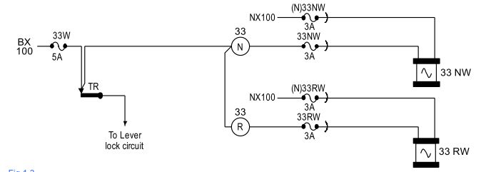
Fig 1.3 shows a typical point control circuit. The outgoing control lines 33NW and 33RW are fed from the main 33W fuse via the Normal and Reverse contacts on the point lever shaft. The lever contacts are arranged so that only one can make them at any one time, thereby only one of the point auxiliary valves can energise at any given time. For this to occur, the lever shaft must be either fully Normal or fully Reverse.
A fault in this circuit could lead to a situation where neither valve is energised. To prevent the points from moving if this were to happen, the ‘D’ valve in the point auxiliary valve is designed to maintain air pressure to the points even when there is no electrical supply to either the NW or RW valves.
What is Point Detection?
Before a passenger train can pass over a set of points under a signalled move they must be electrically proved to be in their correct position and locked. In the case of Four Foot points, there is a single point and lock detector box (P&LD) connected to the escapement slide and both point switches.
This box usually contains six contacts (6 way), three for the Normal detection and three for the Reverse detection. The relevant contacts are made when the facing point lock (FPL) is proved in position, the open point switch is detected open sufficiently and the closed switch detected up to the stock rail within tolerance. This fulfils the third Basic Principle
If any of these three criteria are not met then all contacts in the box must remain broken. We are going to look at the main electrical components involved in the detection circuit, namely the P&LD box and the three-position WKR, before looking at the detection circuits.
The P&LD Box
The Four Foot point equipment can be located on either the left or right-hand side of the negative traction rail. The position of the positive traction rail governs the type of layout to be used as the majority of the equipment should be at continuous rail potential; where possible the continuous rail is always next to the positive rail.
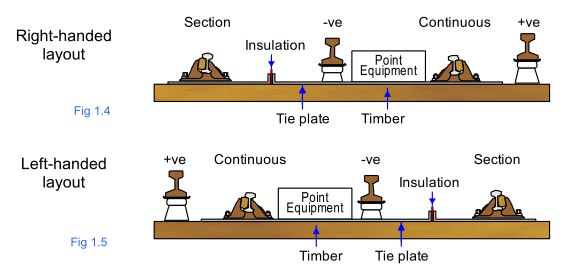
Both diagrams are viewed from the tips of the switches looking into the points.
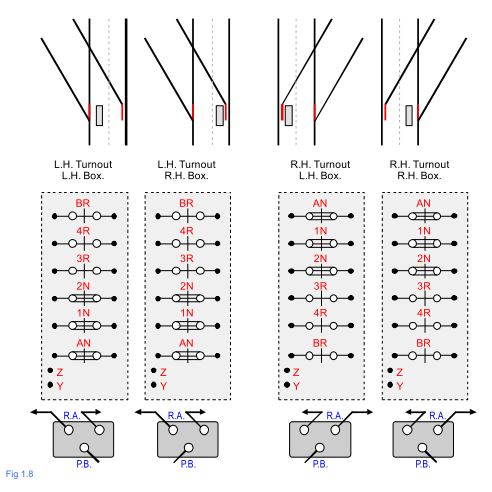
There are two types of six-way P&LD box available and are labelled according to the layout they are to be used with. A left-hand box is for a left-hand layout and a right-hand box for a right-hand layout. Although the boxes are functionally the same they are mechanically different and cannot be swapped. In a Left-hand box the contacts are made (Normal or Reverse) when the radial arms and parabola ball are paraLLeL to one another.
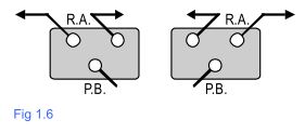
In a Right-hand box the contacts are made (Normal or Reverse) when the radial arms and parabola ball are at Right angles to one another.

The contact numbering in the P&LD box changes according to the turnout of the points. Standing at the tips of the point switches, starting with the contact furthest away the labelling is as follows
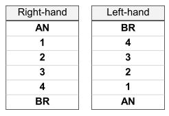
The AN and BR contacts are used in the control of the WL valve. Contacts 1N, 2N, 3R and 4R are associated with the point detection circuit.
A little ditty to remember this is: I (R)(AN) to (L)London (Bridge)
Right-hand turnout (AN) is furthest. Left-hand turnout (BR) is furthest.
A summary of the contact labelling is shown below
All points are shown in the Normal position and viewed from the tips of the switches, facing the points.
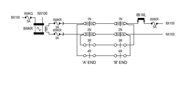
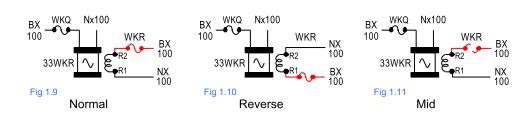
The Three Position WKR
The detection circuit uses a three-position Double Element Vane (D.E.V.) type relay which has two coils (‘Q’ & ‘R’) and twelve contacts (six Normal and six Reverse). Both coils operate at 100V A.C, the ‘Q’ coil being fed directly from a local bus bar and the ‘R’ coil via the P&LD box contacts. By altering the direction of the current passing through the ‘R’ coil the relay will drive either Normal or Reverse. When there is no supply to either of the coils, the relay returns to the mid-position, where all contacts are broken.
Dear Railway Signalling Concepts,
I would like to comment on the above article ‘Railway Point Circuit’ posted on the 4th September 2019, which has the name of Pradhan Mantri Vikas Yojana, attached to it.
Factually it is correct, as it has been directly lifted from training material that is used by London Underground Limited to teach it’s Signalling Staff.
This training material is freely given out to our students for them to study, however I feel that Pradhan Mantri Vikas Yojana has plagiarized this material without any acknowledgment as to it’s source.
I am all for educating people in Railway Signalling, as I am sure that is what the purpose of your site is all about, but please ensure that any further material posted up is credited to the source from whence it came.
kind regards,
Alfred Casarrubios | Signalling Competence Assessor/Trainer | Skills Development
Signalling Training Centre (STC)
London Underground,
130 Bollo Lane, Acton, London W3 8BZ (Building AC02a)
Alfred Casarrubios,
I would like to apologize for the article ‘Railway Point Circuit’ has plagiarized this material without any acknowledgment as to it’s source. it would never happen again.
Kinds Regards,
Railway Signalling Concepts,