Signaling Design Process Thales Projects
References for The Design process under which signalling system modifications shall be undertaken for JNUP project.
1. 3CU 00550 0295 PCZZA
2. 8BH 04002 5034 URZZA
3. 8BH 04002 5033 URZZA
4. 3CU 00550 0215 UNZZA
5. Bulletin B-0550-003
6. Bulletin B- 0550-006
7. 8BH 04002 5518 URZZA
8. LU Standard 2-01203-015
9. RT/E/C/11701
Defining Producer, Checker & Approval Checker
Producer
The following licensed personal are responsible for the production of design.
• Assistant Designer
• Designer
• Principles Designer Or Appropriately mentored un licensed trainee
Checker
• Responsible for the independent checking of design.
• Licensed Principles Designer.
• Appropriately mentored designer.
• Independent from production activity.
Principles Approver
• Responsible for the final approval of the design prior to issue to client.
• known as Approver.
Mentor
• Licensed Engineer responsible for guiding, training, supervising an engineer working outside their limit of competence
IRSE License Competency
Competency Categories:
• IRSE licensed categories are required to undertake designs. Assistant Designer:
• An Assistant Designer is capable of undertaking minor design only.
• All designs should be non conceptual and would be undertaken under the guidance of Licensed Designer/Principles Designer
Designer:
• A Designer is capable of undertaking non conceptual design.
• Capable of designing or modifying the signalling designs from a user specification, and to comply standards and regulations.
• Requires guidance from a licensed Principles Designer in case of conceptual design.
Principles Designer:
• A Principles Designer is capable of undertaking all levels of design and checking activities including conceptual design.
• Capable of designing or modifying the signalling designs in accordance with signalling principles.
• In addition he shall be capable of supervising a design team.
Group Leader:
• A group leader manages a design groups.
• Represents the source of technical clarification for the design team.
Design Checking
Production check
* Self check of design by the producer prior to the handover to checker for independent checking in accordance with LUL Standard E1008.
Independent check
* Checking of design by the independent checker who is independent from the production of the design activity in accordance with LUL Standard E1008.
Principles Approval Check
* Check of the design to validate in terms of standards, safety principles and operability; and the signalling logic with respect to the interface issues and the correct application of equipment in accordance with LUL Standard E1008.
How to do Checking
Production checking
* On completion of production, the producer shall undertake a production check by tick marking each element on a production check copy.
* Once satisfied the state of the design, the producer shall provide a clean copy to the independent checker along with design log.
Independent checking
* On receipt of checking copy, the checker should ensure the familiarity of the design and requirements.
* Check with standards and their currency, site information and scope of design.
Checking Copy Records
• Checking copies of the design shall be tick marked in a unique colour within the department to the specific independent checker.
• Tick marks shall be applied to the individual items.
• Where an error is discovered it shall be clearly marked and provided with error reference number.
Error reporting
• The design log shall be used to record the errors found in the check. This shall be ordered by error reference number and provide brief details of the error.
• The checker shall sign and date the design log.
• On completion of the check, the checking copy and design log shall be returned to producer for update.
• The producer completes the updates, sign in design log and provide fresh checking copy to the checker.
Principles Approval:
• The Group leader or appointed another principles designer shall undertake this checking subsequent to Independent checkers satisfactory completion.
• The approval check shall be undertaken on a checking copy marked as “Approval Check Copy” .
• The approver shall focus on correct application of principles, operating rules and standards.
• The Approver shall record any errors in a design log.
• On completion of approval check and updates the Producer, Checker and Approver all shall sign off office copy and design log.
• The copies are passed on to the UK design team who will perform the design acceptance.
Design Acceptance:
• Signalling design acceptance is one element in the overall assurance process that allows for the safe introduction of the new TBTC system into passenger service.
• The UK design team is responsible for the acceptance of the signal design and delivery of the system to the required standards and levels of operability.
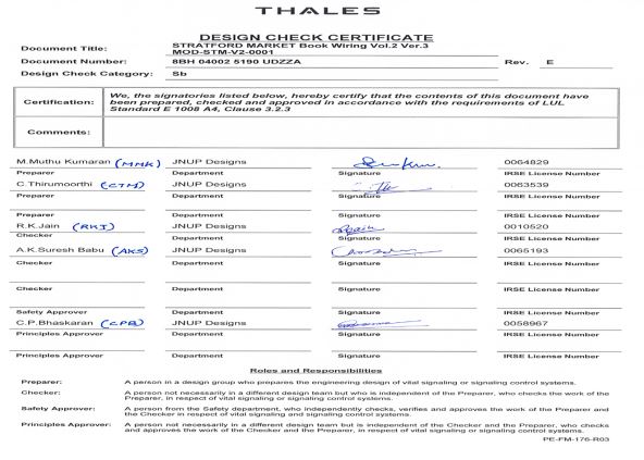
Design Check Certificate (DCC)
• Design check certificate shall accompany each completed design.
• DCC shall includes names, signatures and license details of the staff involved in design, in accordance with LUL standard E1008.
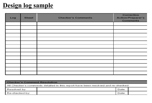
Design log
• The design log is to be created for each design and it should have a unique number.
• The design log containing the details of
Work package
Planned duration
Staff involved
Design brief
Independent check error log
Approval check error log.
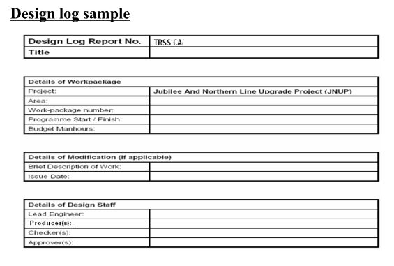
Design log sample
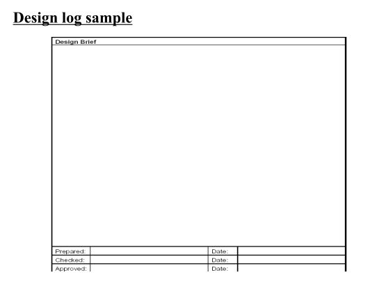
Design log sample
Design log sample

Revision History Sheet

AIR sheet
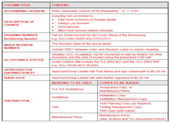
• For details of AIR sheets refer to QA-PRO-606.
• This document describes the requirements for the production, use and control of Approval and Issue Record (AIR) sheets.
• This procedure applies to all book wirings whether sourced from Thales, WRSL and TLL.
Information required to complete AIR sheet
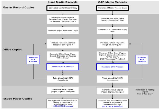
Various Design Copies
Master Record
• It is a source document of the as built drawing.
• This may be a wet signature paper copy, linen, negative or CAD.
• For all CAD master records a certified paper copy shall be produced and retained as an accompanying document.
• Stamped as “Master copy” on reverse side.
Office copy
• Produced upon successful completion of production, checking and approval process.
• Stamped as “Office copy” on reverse side.
• All issue copies are produced from office copy.
Security copy
• Copy of master record.
• This copy is used to recreate the master record in case of cancellation of works etc.
• Stamped as “Security copy” on reverse side.
CDMS ( Common Document Management System)
WEB based database for sharing of documentation used to aid communication between offices.
DDTS ( Distributed Defect Tracking System)
TRSS approval and change control system for all documentation, software and drawings.
System Change Request (SCR)
• For any design, other than a first release SCR must be raised.
• The SCR may be raised in response to the following types of change
a. Comment sheet from TLL
b. Change in source documentation
c. Feedback from Installation & Testing staff
Engineering Change Notice (ECN)
• It is the responsibility of the producer of a design to raise ECN.
• The ECN number must be cross referenced in revision history sheet and title block of each drawing sheet.
• Once the Design has been produced, checked, approved and signed off, the deign shall be submitted for DDTS approval.
• During DDTS approval the Responsible Manager approves and assigns the ECN for safety and quality approval.
• Once safety & quality approval the ECN will go to Publishing.
• The Publishing group will place a full pdf copy of the design in the ‘Published drawings’ directory on CDMS and send the hard copy
with original signatures to the UK document controller for generating acceptance copy for TLL.
• Please note the client is doing ECN process
Design Modification Guidelines
Design Modification
• Modifications are only used once installation has commenced. i.e on issue of installation copy.
• Modification sheets are issued with the following aims:
a. Expediency of issue
b. Clarity of modification
• Modification process requires strict configuration control of all modifications made to issued sheets.
• This is achieved by unique identification and full traceability to the affected drawing sheets.
Mod No: ALC-N392-MOD-xxx-Vy-zzzz
Zzzz is the Modification number 0001 to 9999, y volume No., xxx SER acronym.
E.g: ALC-N392-MOD-NOG-V2-0001.
Modification Register
• The Group leader shall maintain a register of modification serial numbers, recording details of the modification.
• Modification Register includes
a. Serial number.
b. Number of sheets within the modification.
c. Date of issue of the modification
d. The issuing ECN number.
e. The source of the modification (DGN, TST, INS, TLL, OTH: Design Office, Test Log, Installation Log, TLL comments, Others, Respectively).
f. Originator’s Reference (e.g. the Test Log number)
g. SCR raised as a result of the originator’s comments/logs.
h. A brief description or other commentary as required.
Production and issuing
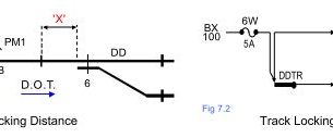
• Modification production shall follow the Red/ Green method of design as detailed in RT/E/C/11701 as applied to the main design works.
• Where appropriate one drawing method can be adopted and shall show only an extract of the affected portion of the circuit along with appropriate analysis sheet extracts. If impractical two drawing method shall be used.
• Further, where appropriate, full drawing sheets, including analysis sheets, profiles, etc. shall be permitted to be re-bordered as Modification sheets.
• In all cases, the sheets shall be issued with a full reissue of the index sheets and Revision History sheets, up-issued to the next revision.
Indexing and Revision Control
• The modification is produced on Mod sheets as described earlier and then the index is updated to show the sheets affected by the Mod sheet.
• The Revision History reflects the issuance of the MOD sheet and that the Index and Revision History sheets have been updated.
• The cover, index and Revision History sheets will always bear the latest revision letter. For every mod, these sheets revision will be incremented.
• Should modification arise during the commissioning, the same process of MOD sheet issue would be applied, with a subsequent reissue of the book wiring at next higher Version for As Built.
TLL Acceptance of Design Modification sheets
All modification packs shall be provided to TLL for Acceptance, using the same process as the bookwiring acceptance submission.
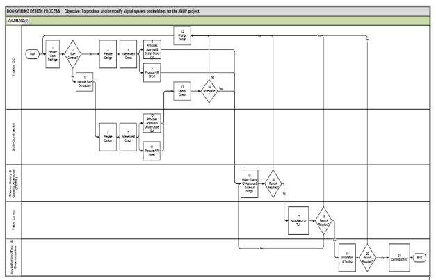
Design process flow
Configuration Management:
• The configuration Management plan is the master document used on the JNUP project and details the change control process.
• When releasing a bookwiring using the ECN provcess, in order to facilitate full configuration management with traceability between TRSS and TLL drawing numbers and revisions, the following process is applied:
1. Designer to produce ECN for release of the 3CU/8BH number on the next bookwiring version (i.e.1 for first release, 2 for next release and so on). On ECN, quote the following additional information (Over and above that normally found on ECN),
a) TRSS Part number and sheets x to y inclusive,
b) TLL drawing number for index sheet,
c) TLL revision of index sheet,
d) TLL bookwiring version, and
e) Description (e.g.STR SER bookwiring Volume 2).
Configuration Management:
2. Designer to create ZIP file of all sheets under the name 3CU/8BH… RevX.zip and create a PDF copy of the index and revision history sheets. Attach PDF of index and revision history sheets and CAD files (in zip file) to ECN. Design log and Design Check Certificate (DCC).
3. Publishing to upload. Pdf file onto CDMS, and transmit original signed copy to UK document controller for creation of the OFFICE COPY, ISSUE COPIES and filling.
Documents to be referred
Design Preparation
• For details on design production and production checking, refer to QA-PRO-603, this document details the practical processes for preparing a design in the form of a new Thales bookwiring.
• It includes,
a. CAD templates
b. Colour convention & stamps
c. Detail transfer
d. Dual sheets
e. BOM (Bill of Material)
f. Asset Register
g. Specific application Design certificate (SDAC)
h. CDM overview.
Design Preparation
• The development of a Volume 2 Thales bookwiring will normally require corresponding changes to existing WRSL or TLL bookwirings.
• These are changes to existing infrastructure and are managed as design changes in accordance with QA-PRO-608.
• The primary output of this process is a design work package that is ready for independent checking, with appropriate documentation.
Independent check
• For details of independent checking refer to QA-PRO-604, this document details the steps to be followed when undertaking the independent check of a prepared design work package.
• The primary output of the process is a fully independently checked design work package ready for submission for Principles approval.
• It includes,
Use of multiple checkers
The design log comments clarification
Rework procedures.
• This procedure will apply to all sheets produced as part of any design work package.
Principles Approval & design Close-out
• For details of Principles Approval, refer to QA-PRO-605, this document details the steps to be followed for the Principles Approval of a bookwiring design that has undergone an independent check for closing out a design work package to prepare it of issue.
• It includes,
The Design Check Certificate (DCC),
Use of multiple Approvers
The design log comments clarification
Design log Error analysis.
• This procedure will apply to all drawings as part fir any design work package.
Management through DDTS
• For details on the Quality Approval process and ECN closure, refer to QA-PRO-607. This document details the procedure to be followed to obtain Thales ‘Q’ approval for a work package produced under the ECN raised when the design work package was established.
• It includes,
Files to include in the ECN
Responsible Manager’s (RM) approval
Maintenance Prints on ECN.
Design changes
• For details on Design Changes, refer to QA-PRO-608. This document details the procedures to be followed for a design change to a Thales bookwiring via Modification packs for a design change to WRSL or TLL (existing) bookwirings.
• It includes,
Colour convention & stamps
Use of Revision letters on Mod sheets
Modification Labels
Bill of Materials (BOM)
Asset Register,
Specific application Design certificate (SDAC)
Existing bookwiring Revision register.
TLL Acceptance
• For details on TLL Acceptance, refer to QA-PRO-609, this document details the procedure to be followed when an
approved bookwiring design package of all types and whether all new or a design change, is to be submitted to TLL for Acceptance and steps to be followed when accepted.
• It includes,
Acceptance Issue package
Certificate of Compliance (CofC)
Management of TLL responses
Link with Installation Release Certificate (IRC)
Installation and testing
• For details on Installation and testing, refer to QA-PRO-610. This document details the procedures to be followed for the preparation and issue of a design work package (whether a new bookwiring or a design change to existing bookwirings) to installation and/ or Test departments and managing and resolution of design queries and/ or difficulties raised by the installation or testing activities.
• It includes the management of,
Installation Log Reports (ILR)
Test Log Reports (TLR)
Commissioning
• For details on commissioning, refer to QA-PRO-611. This document details the procedures specific (including Closure list) to the JNUP project on the Commissioning of the TBTC systems which occurs in two stages,
1. Commissioning of the ‘Cut-in/ COC’ design.
2. ML testing of final TBTC system leading to revenue commissioning and decommissioning of the COC.
• Staged commissioning of TBTC at the migration boundaries.
Records Retention
• Records shall be retained for the duration required by the contract.
• In no circumstances should this be fewer than 7 years.
• Specific record retention requirements are addressed in the reference documentation.
Configuration Management
• The approach is given in the configuration Management plan.
• Details of how this is applied during design and design modifications are contained in QA-PRO-601, QA-PRO-603 and QA-PRO-608.