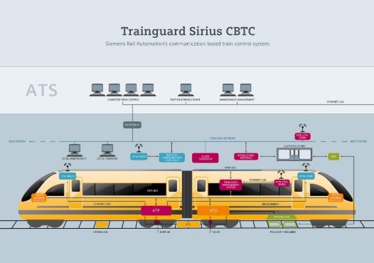
Railway CBTC Equipment
CBTC Components
Vehicle On-Board System:
1. Vehicle On-Board Controller (VOBC)
2. Thales Radio (composed of Mobile Radio, Switches for
Trusted and Untrusted Networks and Security Device);
1. Train Operator Display (TOD);
2. Transponder Interrogator (TI) with transponders;
3. Proximity Sensor with proximity plates;
4. Speed Sensors; and
5. Accelerometers.
Wayside Equipment:-
1. WRU – Wayside Radio Unit
2. Axle Counter Block
Vehicle On-board control system
It is the core on-board component of the vital train control Allows driverless train operation, by implementing
automatic train protection and Automatic train operation functionality, Including safe train automatic or manually driven movement, Including driverless turn back and Accurate station stopping, Automatic door operation, and protection.
The VOBC is a vital ATP component of the SelTrac CBTC system designed and built redundantly for safety and availability. Each train consist has 2 VOBCs installed, one at each end, in a hot-standby configuration, ensuring a high level of availability. In its operation, the VOBC uses transponder tags (which provide train relocation reference), which are installed along the running tracks.
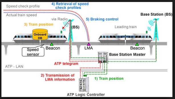
Train Speed and Movement Authority
The On-Board CBTC equipment supervises a controlled train’s ability to stop within the Movement Authority. If the train is at risk of traveling beyond the Movement Authority, the VOBC commands EBs (Emergency Brakes).
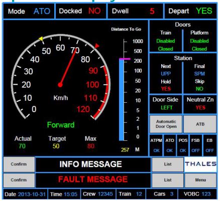
Train Operator’s Display
The primary function of the TOD is to allow the train Operator to read the status of various CBTC subsystems and other information such as distance to go, actual speed, and target speed There is one TOD installed in each cab of the train.
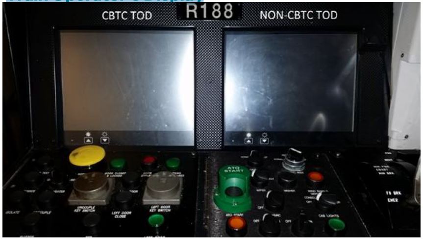
The primary function of the TOD is to allow the train Operator to read the status of various CBTC subsystems and other information such as distance to go, actual speed, and target speed There is one TOD installed in each cab of the train Speed information (Maximum permitted speed, Actual speed, and New target speed);
Distance to the next stopping point;
Dwell countdown timer;
Doors status;
Fault information (Train loses position, Train loses “Closed and Locked” status of the doors, Train loses communication with the ATS or ZC, etc.);
Train Operating Mode information; Door Control Mode Information.
Transponder Interrogator Unit (TIU)
There is one TIU per VOBC unit. The TIU is used to read transponders located at the trackbed and provide the system with information used to determine the position of trains in the system. This TIU system consists of four fundamental components:
Interrogator;
RF module;
Antenna; and
Transponder.
Speed sensors
There are two-speed sensors per VOBC unit and both are required for operation. Each speed sensor channel generates two output streams which are out of phase by 90 degrees. The two output streams provide the number of pulses per wheel revolution. The frequency of the pulses is proportional to the angular speed of the train wheels. Output from the speed sensor channel is used as input to Peripheral Processor Units within the VOBC for detection of zero velocity, and determination of train speed traveled distance, and travel direction.
Accelerometers
There are two accelerometers per VOBC unit and two accelerometers are required for operation. As the accelerometers are mounted on the car body, the accelerometer indicators are used to measure the acceleration and in conjunction with speed sensors, to measure train speed and traveled distance.
Proximity Sensors
One proximity sensor is provided per each VOBC unit. The proximity sensor is used to detect the wayside installed proximity plate The proximity sensor provides positive confirmation to the VOBC that the train is properly aligned at a station, pseudo-station or storage lane.
Mobile Radio Unit
The Mobile Radio Unit is a CBTC component used to provide an interface from VOBC to the ZC and the ATS. There is one Mobile Radio Unit located at each end of the train. Each unit is individually addressable on the network. The Mobile Radio Unit consists of MR, network switch and Security Device. MRUs are installed at both ends of the train to maintain communication with the wayside. In case of failure of one of the radios or loss of radio signal to a WRU at one end of the train, the system is still fully functional by maintaining communication with a wayside using one radio unit.
Antennas
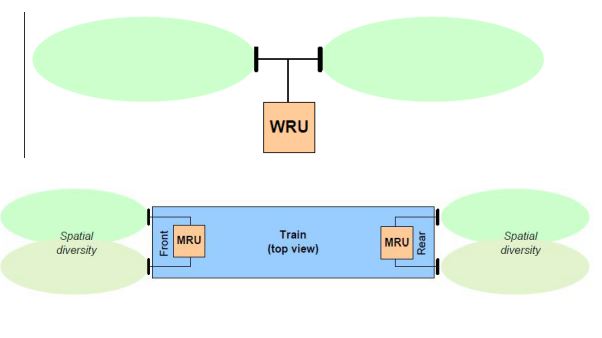
On-Board, high-gain patch antennas look outwards from the front and rear of the vehicle and “illuminate” (or receive from) only that section of the guideway directly ahead of, or directly behind, the train. Two such antennas are used at each end (i.e. a total of four antennas per vehicle) in order to provide propagation path diversity at that end. The MRU at each end determines which antenna of the two is providing the best link at any time.
WRU (Way Side Radio) Unit
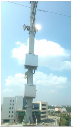
The WRUs are inter-connected in a ring topology and this ring is coupled to the untrusted backbone ring via inter-ring switches that run a “ring coupling” redundancy protocol. The layout is designed to provide overlap between the WRUs in terms of coverage, such that the failure of a single radio does not cause any degradation in performance. WRUs are strategically placed at certain intervals so that at any point on the guideway the MRUs are capable of communicating with at least two WRUs. This design ensures that full coverage is maintained even in such cases as a failure of every alternate WRU, failure of a fiber optic cable, and failure of a power supply.
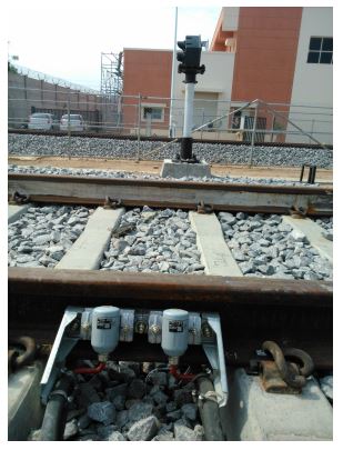
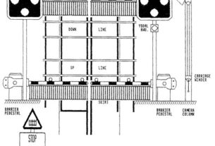
Axle Counter Block Functioning
For normal CBTC operations, axle counter Blocks are used as a secondary detection system and not used for safe train separation. The secondary localization system is used for tracking failed-equipped trains and non-equipped trains.
Axle Counter Detection Point
Signal Layout:
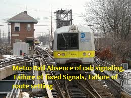
Wayside signals are used to restrict movements for the manually driven non-controlled trains. The following signal indications are defined based on the three aspect signalling:
1. Red aspect = stop
2. Green aspect = permissive with reduced speed for Non Communicating trains.
3. Violet aspect = permissive with normal speed for CBTC trains
Signals

This website is very informative for anyone who is working for railway signalling. I really found the supporting visuals very useful and easy to understand the topic – I mean it is hard to find technical contents with appropriate visuals mostly.
I appreciate the efforts of the author/owner and thanks so much!
Thank u sir
What is RESET VOBC
Very informative. Keep it up .
tx
Hi,
I would like to request to kindly arrange to provide CBTC Antenna mechanical design data for reference. I am signalling engineer in Mumbai Metro line 4 General Consultancy.
Regards.
ok i will try.