Railway Train stop
Railway Train stop :- What is a Trainstop?
The trainstop is a vital part of Automatic Train Protection used at all stop signals where trains could be required to stop. It is an electro-pneumatic failsafe mechanical device used to apply the emergency braking system on any train that passes a stop signal in error (when the stop signal is at danger).
How it works?
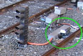
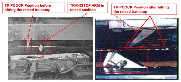
The trainstop is positioned on the right hand side of the track and is installed to a gauge in the direction of travel. A mechanical arm with a flat head is raised to a position to engage with the tripcock arm on the train. On contact, the tripcock arm is pushed back and operates the trains emergency brake. In case the stop signal is already cleared, the mechanical arm gets lowered (OFF) and does not engage with the tripcock arm.TRAINSTOP
What is a Tripcock?
A tripcock is the device on the front of every manually driven train which, when in the lowered position and coming into contact with a trainstop arm in the ‘ON’ position, causes the brakes to be applied. It is an essential part of train protection and safety operation for trains operating over LUL lines.
Types of Trainstop:
1. Fixed Trainstop
2. Controlled Trainstop
Types of Controlled Trainstops:
1. HO open section use
2. HT Tunnel use
3. J open section use (oil filled self lubricating)
4. K Tunnel use (oil filled self lubricating)
Types of GE valves
1. 100v 33 1/3 Hz: Coloured red
2. 100v 125Hz: Coloured silver
3. 100/110v 33 1/3 – 125 Hz: Coloured red and silver (universal)
Where controlled and fixed Trainstops are used?
1. Stop signals on running lines (excluding pre-set shunt signals) and shunt signals shall be provided with a controlled trainstop device which operates in conjunction with the signal.
2. Some controlled trainstops are not associated with stop signals but used for speed control.
3. Trainstop is not required for repeating signal.
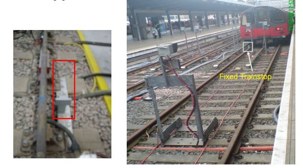
4. Fixed Trainstops are used at end of siding and terminal platform stations (Buffer stop).
Fixed Trainstop:
A fixed trainstop with no moving parts placed at dead end lines to ensure that emergency brakes are applied should the train overrun the stop position.
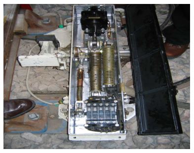
Controlled Trainstop operating principle:
When the signal is at danger, the trainstop is said to be at ‘ON’ with the trainstop head in the up position, raised and held by a heavy-duty spring coil. When the signal is at proceed, compressed air is applied to the trainstop air cylinder by energising an electro-pneumatic valve. This action operates a piston, which is pushed against the spring to lower the head to the down position. The trainstop is now in the proceed or ‘OFF’ position. When a train passes a signal, the signal is replaced to ‘ON’ and feed to electro-pneumatic valve gets cutoff. Now the trainstop head return back to raised (ON) position by the compressed spring.
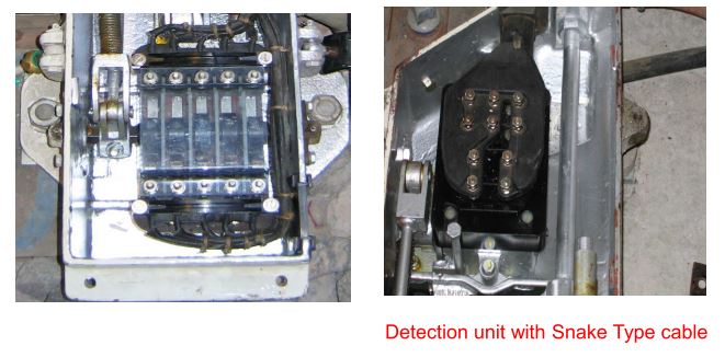
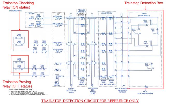
Trainstop ON and OFF detection contacts:
The trainstop is provided with inbuilt detection unit to detect the position of trainstop arm. whether “ON” or “OFF”.
1 & 1.1 = ON
2 & 2.2 = ON
3 & 3.3 = OFF
4 & 4.4 = OFF
5 & 5.5 = ON
In the event of the trainstop head breaking off, the neutralizing spring will maintain all contacts in their open position.
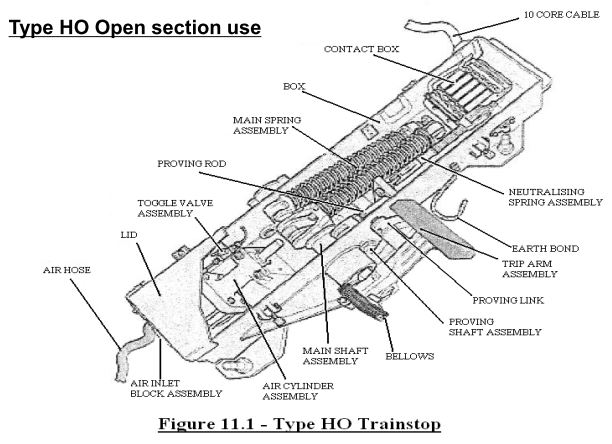
HO type:
A trainstop, fitted on outside sections of railway (SURFACE LINES). The trainstop arm is fitted to the side of the unit. Lubrication is undertaken manually by a technician.
Type HO Open section use
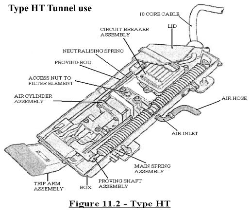
HT type:
A trainstop, fitted on tunnel section of railway (TUNNEL LINES). The trainstop arm is fitted to the front of the unit. Lubrication is undertaken manually by a technician.
Type HT Tunnel use
“J” type:
A trainstop with mechanical lubrication, fitted on outside sections of railways (SURFACE LINES). The trainstop arm is fitted to the side of the unit.

Type J Outdoor use (self lubricating)

“K” type:
A trainstop, with mechanical lubrication, fitted on tunnel sections of railways (TUNNEL LINES). The trainstop arm is fitted to the front of the unit.
Type K Tunnel use (self lubricating)

Trainstop protection:
• Stop signals shall be equipped with a trainstop
• Trainstop is positioned on the right side of the track and installed to gauge in the direction of travel.
• The head of the trainstop shall be detected by diverse means in order to prove that the trainstop head is raised or lowered. This proving shall be used within the signal interlocking functions.
• The trainstop arm shall be raised in the event of electrical or air supply loss or both.
Trainstop proving
• After train passing a signal, if the trainstop was to fail in the down position it could have very serious consequences. There should always be at least one trainstop in ‘ON’ position between two trains. To achieve the above, trainstop proving circuit is designed so that a train should never approach a trainstop in the ‘OFF’ position that should be in ‘ON’ position.
• All trainstop shall be proved to have returned to the fully ‘ON’ position after every occasion that they have been lowered.
Trainstop Release:
In the case of bi-directional layouts, where a train is to pass a signal reading in the opposite direction, the trainstop shall be lowered to prevent the train from being ‘BACK TRIPPED’ by the trainstop engaging with the tripcock in the trailing car. To facilitate this arrangement the trainstop shall normally be located at a track circuit boundary. So, that when the train occupies replacing track circuit of the opposite signal the trainstop will be lowered and returned to ON position after the passage of a train.
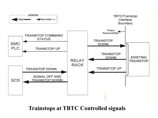
Trainstops at TBTC Controlled signals :
• The command to lower the trainstop for normal or reverse direction movements will be output from the SCS. This will be a separate output from that which clears the signal, in order that wrong road lowering can be done without clearing the signal.
• The trainstop ‘OFF’ status will be provided (combined with signal aspect status) to the SCS, for the purpose of setting LMAs past the trainstop during migration.
• The trainstop ‘ON’ status and command status (i.e. whether or not the trainstop is being commanded down) will be input to the SMC PLC in order to alarm a failed down trainstop.
Migration Boundaries Entering TBTC Territory :
* The existing trainstop at the starter signal will be retained(Re-used) and two additional trainstops will be installed in advance of the signal at TBTC boundary. The signal trainstop will be controlled down by the same SCS output which is used to clear signal.
* The two additional trainstops will be controlled down by separate SCS outputs at the same time as the signal is cleared.
* The signal trainstop will be held down until the signal is replaced to danger. Each additional trainstops will be held down until the front of the train has passed it. The starter signal and Low speed Train stop will be proved to returned to the ‘Up’ position by inclusion in home signal for the platform or in TQ circuit.
* Failure ‘Down’ of the High trainstop will be alarmed, but will not prevent a train approaching the starter signal.
* The signal trainstop ‘OFF’ status will be provided (combined with signal aspect status) to the SCS, for the purpose of setting LMAs past the trainstop during migration.
* The ‘ON’ status and command status (i.e. whether or not the trainstop is being commanded down) of each trainstop will be input to the SMC PLC in order to alarm a failed down trainstop.
Migration Boundaries Leaving TBTC Territory :
* The signal and trainstops at Migration Boundaries Leaving TBTC Territory will be controlled by existing signalling system and monitored by TBTC through the existing trainstop detection relay(VCR/VPR) contacts.
* The trainstop ‘ON’ status will be provided to SCS. In combination with the ‘Signal OFF’ status input the train will only be permitted to change into TCP mode if the starter signal is off or the trainstop is up.
* Trainstop ‘OFF’ status will be provided to SMC PLC for alarm raising purpose only.
* After migration, except for the Mixed Mode Area shared routes not fitted with an ATC aspect and controlled by the Interlocking Machines, all trainstops will remain in the raised position for moves by controlled trains not fitted with tripcocks. For moves by tripcock fitted controlled trains in either direction the trainstops will be lowered until the tripcock has passed.
* For the Mixed Mode Area shared routes not fitted with a ATC aspect controlled by the Interlocking Machines the trainstops will lower for all train moves.
* Trainstops will be provided at transfer locations where the train is transferred from TBTC area to existing system and transferred from existing system to TBTC area.
* In the TBTC – signalled area during migration trainstops will be provided at departure ends of all stations and reversing locations used for timetabled reversing. These trainstops will be lowered for TBTC controlled train moves. These trainstops will be removed when the complete line has been migrated to TBTC signalling.
* In the Mixed Mode Area all signals with or terminating tripcock train routes, fixed red lights terminating tripcock train routes and the out of gauge train detector will be provided with trainstops. These trainstops will be lowered for valid tripcock routes and for moves by TBTC controlled trains fitted with tripcocks.

Trainstop Symbols in SSP: