Railway HR POINT NCR RCR WLR PCR Circuits
At HR stage all the conditions to be satisfied for clearing a signal are proved.
- Crank handles are ‘in’, i.e. proved by CHLRs up and CHFRs down.
- Route Release Relays have de-energized after the last train movement i.e UYR1, UYR2 etc., are down.
- No cancellation is initiated i.e. JSLR down.
- Interlocked LCs if any in the Route and overlap are locked and closed against Road traffic (LXPR up) and held locked till the passage of that train is over.
- Conflicting signals are at ‘ON’ is proved by proving the front contact of ASRs or back contacts UCRs of conflicting signals.
- All points in the route, overlap and isolation are set and locked i.e. Concerned NWKRs, RWKRs are in up condition.
- Concerned to its own signal i.e
– RR is up
– UCR is up
– ASR is down
– One signal – one train feature (TSR up)
* All Back lock & and controlling tracks are clear i.e. TPRs concerned are up.
* Signal ahead is not blank (GECR up or RECR/HECR/DECR UP)
* Route Indicator lamps are not lit for straight line (UHRs / UGRs and UECR down) compulsory in case of Junction type Indicator
* Route Indicator lamps are lit for loop lines (UGR or UHR and UECR up)
* Sidings in the route & overlap are kept normal and held (siding KLPR/NPR up).
* Cross protection is provided for the signal control relay, by the Front contact of ASR or Back contact of UCR.
* Double cutting is provided by UCR up & ASR down
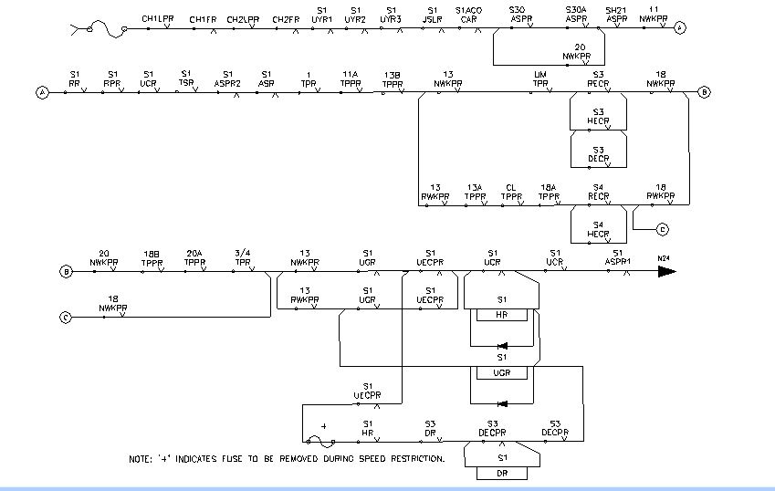
HR CIRCUIT FOR S1
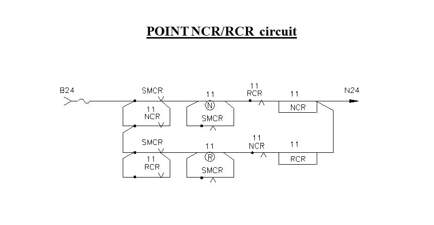
POINT NCR/RCR Circuit
* NCR is energized for normal operation of point when point knob is turned to normal.
* RCR is energized for reverse operation of the point when point knob is turned to reverse.
* The normal and reverse contacts of knob are bridged by SMR back contacts, thereby point remains in last operated position when the SM locks the panel.
* Either NCR or RCR always remains in energized position till the point knob is turned to the other side.
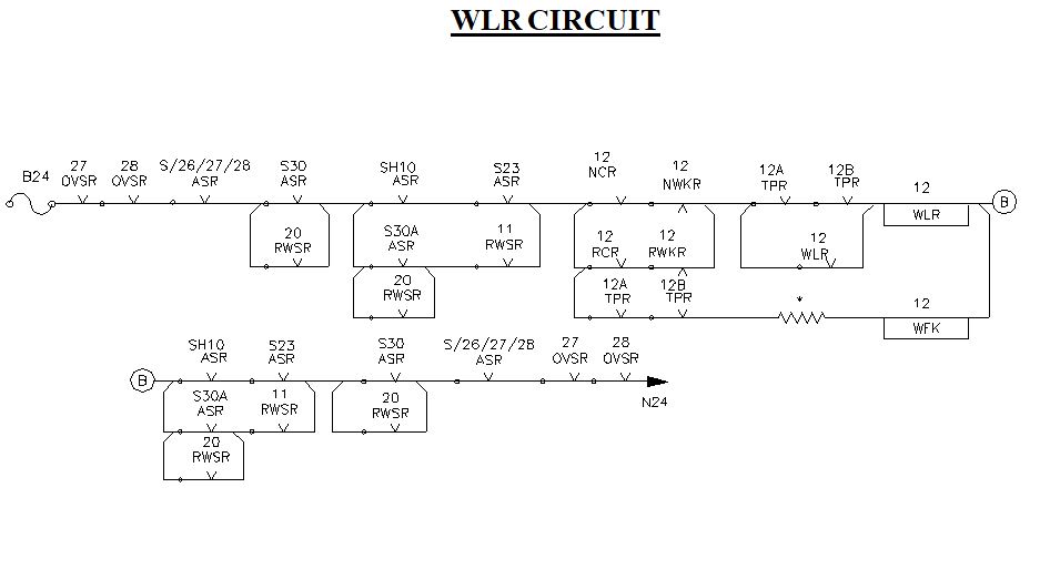
WLR CIRCUIT
* WLR is normally a de-energized relay. So normally the point is locked electrically.
* WLR relay gets energized whenever the point knob is turned from R to N i.e. NCR energized or point knob turned from N to R i.e. RCR energized, provided all other conditions are satisfied.
* When the point is set and indication relay is energized, drops the WLR and locks the point electrically.
* In WLR circuit, all the signal ASRs in whose route that point is included, are proved in up condition.
* All OVSRs for that point are proved in up condition.
* Track locking is proved by its point zone tracks.
* Track locking is bypassed by its own WLR front contact as stick path. So that once a point movement is started, it completes its operation even the track down occurs during operation. In some railways crank handle ‘IN’ is also proved.
* When ever the signal is taken off, the concerned ASR drops and locks the point i.e. it does not allow WLR to pick up though the point knob is turned.
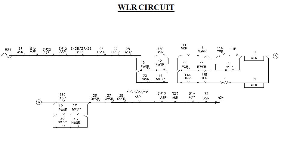
WLR CIRCUIT
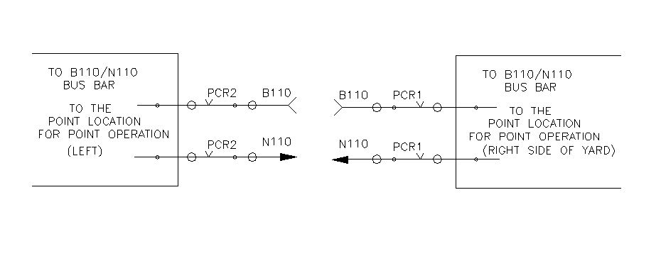
PCR CIRCUIT
With WLR up, the PCR heavy duty relay picks up

With PCR up 110v DC is extended to point location.
Sir point sequence batay
And lc get circuit about
ok