The Detection Circuit
Figs 1.12 and 1.13 show a typical detection circuit for a single ended right-handed set of Four Foots.
To change the phasing of the ‘R’ side the BX and NX feeds need to be changed by 180º (R1 and R2 feeds swapped around). In the detection circuit this is achieved by using loops in the P&LD box as shown in Fig 1.12.
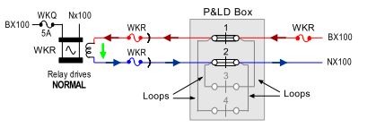
In Fig 1.12 the points are shown detected in the Normal position. The BX and NX supplies to the WKR are fed over contacts number one and two respectively. The arrows represent the direction that the current is flowing through the coil at a given moment in time (used for
explanation purpose only).
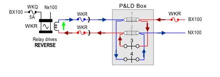
In Fig 1.13 the points are shown detected in the Reverse position. The BX is fed over contact number three and the NX over contact four. The arrow is now shown pointing in the opposite direction as the phase has been changed by 180º.
At older sites, the feed for the ‘R’ coil is taken from a fuse bay in a kiosk or location adjacent to the points. At newer sites the ‘R’ coil supply originates in the IMR, feeds out to the points and returns back to the relay in the IMR.
In the case of a double ended set of points, the WKR needs to detect that both ends are Normal or both ends are Reverse.
To differentiate between the two sets of points they are labelled with a suffix of ‘A’ or ‘B’. The ‘A’ points being situated nearest to the controlling IMR and the ‘B’ end furthest away. A double ended layout may typically be labelled 33A and 33B.
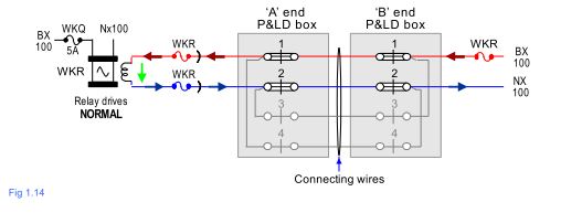
The detection circuit for a double ended set of points requires additional wiring to connect the ‘A’ and ‘B’ end P&LD boxes. The loops are now split between the two boxes, an example of this is shown in Fig 1.14.
The WL Control Circuit
The WL control circuit can be sub divided into two parts:
1. Track locking
2. WL valve control
Track locking
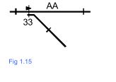
Every set of points which has a passenger move over them, must be track circuited throughout their entire length. The associated section of track is known as the point locking track circuit. Fig 1.15 shows AA track as the point locking track circuit.
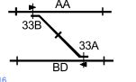
In some situations such as double ended points more than one track circuit may be used. Fig 1.16 shows AA and BD tracks as the point locking track circuits.
When the track circuit(s) is (are) occupied, the WL cannot be energised and the points remain locked to prevent them from moving under a train. This fulfils the fourth requirement in the basic principles.
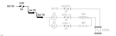
Fig 1.17 indicates how the point locking track circuit contacts are wired into the WL control circuit. The example shows two point locking tracks, for a single track, only one TR contact would be used.
WL Valve Control
When the point lever is moved from say N → R to throw the points over, there is a sequence of events that must occur to enable the points to operate correctly.
A simplified event list for this N → R movement is shown below:
1. Normal point auxiliary valve de-energises.
2. WL valve energises retracting the WL from its port.
3. Reverse point auxiliary valve energises and points move towards Reverse Position.
4. WL valve de-energises and WL dab drops and rests on the WL slide.
5. Points reach fully Reverse position.
6. WL dab enters Reverse port on the WL slide.
The control of the WL has two stages, it must be energised before the points are thrown and then de-energised to allow the dab to enter the destination port.
The ground lock (WL) needs a separate energy source to activate it and unlock the points, but does not need an energy source to re-lock the points.
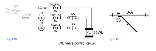
Fig 1.18 is an example of the WL control circuit for a single end, right-hand point turnout. The RC and NC lever bands control the pick-up of the WL valve. The AN and BR contacts are used to control its de-energisation once the points start to move.
The Ground Lock (WL)
Engineering standard E7152 A4 (Maintenance of Points) defines the Ground lock (WL) as: An independent point lock which keeps the points locked to guard against incorrect operation in the event of certain types of failure (generally only fitted to pneumatic systems).
Pneumatic points are held locked in position by air supplied to the motor from a ‘D’ valve in the point auxiliary valve. The design of the ‘D’ valve is such, that if the electrical supply is removed, the air supply is still maintained to the points to prevent them from moving.
If however the air supply is removed, there would be nothing to prevent possible movement of the escapement slide and consequently the points.
A train travelling over a trailing set of points that are not home and locked will cause damage but is likely to stay on the track and not de-rail. If facing points move under a train there is a high risk of derailment and the possibility that some carriages will ‘jack-knife’ (some take the left route and some take the right). With such serious consequences there is clearly a need to have a secondary means of locking facing points to protect them in the event of a loss of air.
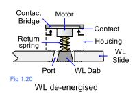
The WL is an air operated piston controlled from an independent electro pneumatic valve. When the valve is de-energised, a dab on the end of the piston is pushed by a return spring into a port on the WL slide as shown in Fig 1.20.
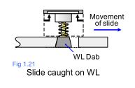
If the slide starts to move, it will catch on the dab and the point escapement slide will not be able to move as shown in Fig 1.21.
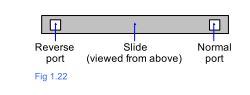
The WL slide has a port at either end so that the WL can lock the points in the Normal or Reverse positions as shown in Fig 1.22.
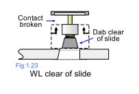
When the WL is energised, the air motor retracts the dab from the port (compressing the spring) and the slide is free to be moved (Fig 1.23). The design of the electro pneumatic valve is such that a loss of the electrical or air supplies will leave the points in a fail-safe condition (WL engaged in the port).

what is BX 100 & NX 100 mean ?