Relay Rack Design JNUP Thales Railway
JNUP Relay Rack Design
* Relay Rack Overview
* Design Principles
* Design Features
* Circuit Principles
* RS Overview
* Points Overview
* RGI
* SPK
* Reference Documents
RELAY RACK OVERVIEW

Typical SER Relay Rack Connections
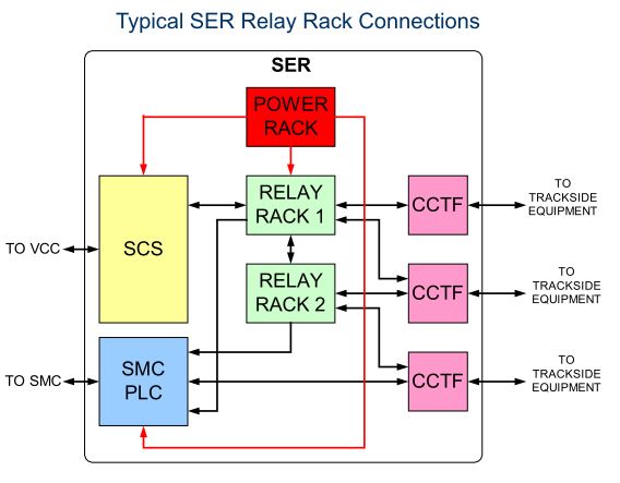
* In the SELTRAC system, the relay rack is the interface between the trackside equipment and the SCS.
* It passes commands from the SCS to the field equipment (e.g. move points)
* It passes information from the field to the SCS (e.g. point detection)
* It also performs a small amount of logic independently of the SCS (e.g. RS aspect selection)
* The relay rack also provides inputs to the SMC PLC
GENERAL DESCRIPTION
* Normally there are two relay racks per SCS.
* Plug connections are used on the relay rack for connections between the SCS and relay rack 1.
* Plug connections are not used anymore on connections between relay rack 1 and relay rack 2 – wires terminate directly on relay contacts or busbars.
* A CCTF (Control Cable Termination Frame – separate from the relay rack) is used to terminate the external cables.
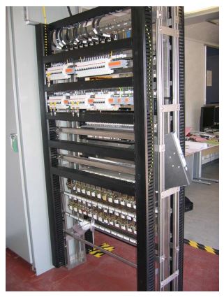
* The relays used are British Rail relays, generally to BR specification 930 or 960 series.
* The wire used is 1mm 2 copper wire with two layers of insulation. The insulation is designed so that it will not give off smoke or poisonous gas if there is a fire.
* Power supply transformers are on a power rack separate from the relay racks
* Rack 1 contains the power busbars, which use miniature circuit breakers (MCBs) instead of fuses for circuit protection, as well as relays
* Rack 2 contains relays only
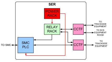
* At stations where there is no SCS, we use a half-width relay rack.
* This relay rack controls and monitors the local:
Current On Line relays.
Rail Gap Indicators.
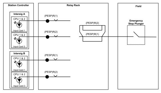
Platform Emergency Stop Plungers (PESPs).
Station Control Room Panels.
Traction Indicators.
* A repeat relay circuit sends the status of the PESPs to the equipment room with the controlling SCS
POWER SUPPLIES
* The relay rack normally receives 2 separate supplies from the power rack:
110V AC is used for circuits which leave the equipment room.
50V DC is used for circuits which stay in the equipment room.
* These supplies are connected to busbars on the relay rack, using miniature circuit breakers on the positive leg and terminals for the negative leg.
* Also the SCS supplies 24V DC to the relay rack for the INTERSIG input circuits, although this supply is not connected to a busbar.
RELAY TYPES
•British Rail specification relays are used.
•The relays operate at 50V DC.
•Single and twin relays are used.
•Contactor relays with heavy duty (high current) front contacts are used for controlling secure busbars
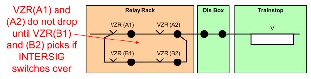
•Relays controlled by INTERSIG outputs (except point outputs) are normally slow release relays (550ms delay). This is to make sure that the trackside equipment controlled by the relays is not affected by INTERSIG switchover (see below).
AC LINE CIRCUITS
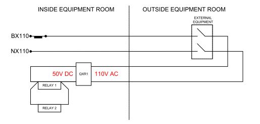
Because the London Underground system uses DC electric power for the trains, to avoid problems with interference from this power, it was decided that all signalling circuits that go outside the equipment room would use AC power (at 110V).
* To match the 110V AC power with the 50V signalling relays, a QXR1 transformer rectifier is mounted on the relay rack for each external circuit.
* Each QXR1 can power two QN1 relays.
CCTF
* The CCTF is the ‘Control Cable Termination Frame’.
* It is an enclosure fitted with four columns of miniature circuit breakers.
* CCTFs are used to terminate all of the relay rack and SMC PLC cables that leave the equipment room.
* All circuits that leave the equipment room must pass through a 6A circuit breaker in the CCTF (positive and negative legs).
* This circuit breaker is to protect the equipment room from any fault current that might get into signalling cables from the traction power rails.
* The CCTF also contains an earth bar for terminating the cable screens and shields.
* Note that there is also a DCTF (Data Cable Termination Frame) in the SER for terminating data cables (for loop transmissions etc.).
DESIGN PRINCIPLES
For vital circuits, the JNUP contract requires that:
* A single failure should not cause an unsafe situation.
* Failures should be detectable. If not detected immediately, the failure should not cause an unsafe situation if a second failure occurs.
* All circuit design shall provide protection against any combination of open circuits, short circuits, partial open circuits, partial short circuits, oscillations or any other known failure modes of specific components.
* All circuits which enter or leave an SER shall be configured to prevent multiple earths or cable faults from by-passing a part of the circuit.
Relay Diversity(1)
* A BR relay is not reliable enough to meet London Underground’s very high safety targets.
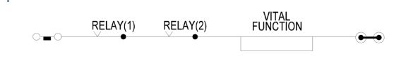
* If a single relay failure could result in an unsafe situation (i.e. most circuits), two separate relays must be proved in correspondence to operate each vital function.
* If one of the two relays fails in the ‘up’ position (due to mechanical failure or contact weld), the vital function (e.g. trainstop) will not operate unless the other relay is also up.
* We do not consider that both relays can fail ‘up’ at the same time (too unlikely).
* We can assume that if one relay fails, the other will continue to operate correctly.
* How can we detect if one of the relays has stuck ‘up’?
* We use relay diversity on the SCS output relays.
* We also have diversity of outputs in the SCS, as one output failure could be dangerous (we use 2 outputs per function).

* We use relay diversity on the SCS input relays.
* We also have diversity of solid state inputs in the SCS, as one input failure could be dangerous (we use 2 inputs per function).
Earth Screened Concentric Cable
* Vital circuits that leave the equipment room are normally carried on earth screened concentric cable.
* A single pair is shown below.

* The central (BX) conductor is surrounded by the return (NX) conductor.
* The fault screen, connected to earth, surrounds each BX/NX pair.
* A 3 pair cable is shown below.
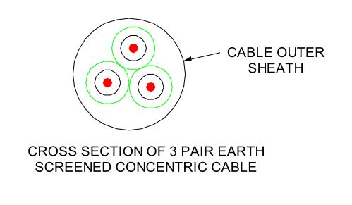
* The design of the cable makes it possible to detect cable faults.
* Because the BX conductor surrounds the NX conductor, any short circuit between these will trip the circuit breaker.
* It is NOT permitted to use a central conductor without connecting the return conductor.
* Any short circuit fault between the NX conductor and the fault screen will raise an alarm on the earth leakage detector.
* Earth screened concentric cables are difficult to bend and are not suitable for installation in all situations.
* Vital circuits in platform areas (e.g. PESPs) do not use earth screened concentric cable because the cable routes are not suitable.
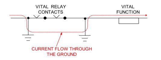
Earth Fault Detection
* Earth faults are caused when cable damage causes the circuit conductors to be electrically connected to the ground.
* They are dangerous because if there is more than one fault, then vital controls can be bypassed.
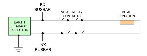
* There are two different methods we employ to detect earth faults on circuits.
* 99% of circuits will be ‘floating’ with earth leakage detectors monitoring the power supply.
* ‘Floating’ means there is no connection between BX or NX and earth.
* If the circuit leaves the equipment room, the relay contacts will be double cut.
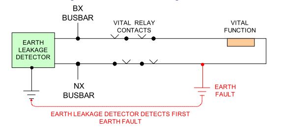
* The earth leakage detector will raise an alarm when the first earth fault is detected on BX or NX leg.
* Note that a single earth fault is not dangerous
* Because there will be many circuits powered from the busbar, the maintenance technician has to test each one until the fault is found.
* An alternative to ‘floating’ supply with earth leakage detectors is the ‘earthed NX’ supply
* This will be used for chairlock point machine detection circuits only (because the chairlock does not have enough detection contacts to double cut them)
* In this approach, the NX is connected to earth and all relay contacts are put in the BX leg only.

* Because there is a connection between NX and earth, any earth fault on the NX conductor will not be detected, but will not be dangerous.
* Any earth fault on the BX conductor will trip the circuit breaker.