Railway WL Control Circuits
If a conventionally wired set of points were thrown from N to R and the Reverse contacts did not make, due to a mechanical fault or a badly adjusted indication arm for example, the WL would drop in to its port and the WKR will not energise. If an attempt is now made to return them to the Normal position, they will fail, as the WL cannot pick up due to the broken AN/BR contacts in the P&LD box. The points would now be stuck in the Reverse position.
This situation can be avoided if the WKR contacts are used to control the WL, instead of the conventional AN/BR contacts in the P&LD box. The WL Control circuits on flat bottom four foot points will allow the points to be thrown back to their original position in the event of no detection when the points are thrown over the opposite way.
Fig 4.3 shows the WL Control circuit for a set of double ended flat bottom four foot points.
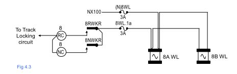
With the points laying Normal the NWKR is energised and the RWKR de-energised. At this point there is no feed to the WL. When the point lever moves from N to R, the RC lever band makes and the supply feeds over the down contact of the RWKR to pick up the WLs. When the lever reaches the R position the RW valve energises and the points throw fully Reverse.
At this point the P&LD box contacts would normally make and pick up the RWKR which in turn would then drop the WL in to its port. If, as in the earlier scenario, the P&LD contacts did not make the RWKR would not pick up and therefore the WL would remain energised. This would now mean that the points could be returned to the Normal position where they would regain indications
It should be noted that because the WL is controlled over a down contact of the appropriate WKR it will pick up when ever the relay de-energises.