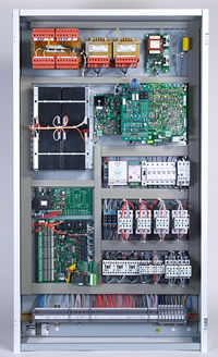
Railway Signalling Relay and Circuits nomenclature Presentation
Equipment Identity
Consistency should be maintained for nomenclature marking or labeling on the equipment in circuit diagrams. Terminals of an item of apparatus should be uniquely identified. Terminal numbers/letters should appear as suffixes to the equipment code. A position code may be given for identifying the location of the equipment. (See figure M3 in page M14)
e.g. 206 NLPR
Identification No = 206
Nomenclature & naming of equipment = NLPR
Arrow on the relay coil indicates a biased relay, which is used in polarized circuits.
Repeat Relays
Normally the first repeat relay should be denoted with “P” added before “R” in the name of relay. Subsequent repeaters should have the appropriate repeater no inserted before’P’.
e.g. AB TPR, AB T2PR
Where there are repeater relays operated simultaneously and provided in parallel, they are named as :
AB TP(1)R; AB TP(2)R etc.
Where repeat relays are derived from back contact of primary relays they are named PZRs.
Special Relays
“Z” used in relay name indicates a special relay. Design details should contain the meaning of the specific ‘Z ‘ except where the name is in common usage. Relay name should be able to indicate the function of the circuit, to eliminate misunderstanding and to assist the maintainers.
Circuit Names
It is the practice to give a unique name to each circuit, identified by the function of the circuit or number and identity code of the operating equipment.
Return conductors are suffixed ‘N’ or ‘NX’ .Polarised circuit conductors with suffix of (1) and (2),Supply conductors with (B) and (N) or (BX) and (NX)
Through Circuits
Through circuits shall show relay contacts, equipment and disconnection points at remote sites, fuse, or terminal details.
Examples of Red/Green works for wiring alterations are in Figures M7 to M10.
