Railway SCS to Relay Rack Interface – JNUP Thales
SCS Electronics Rack/Relay Rack Interface
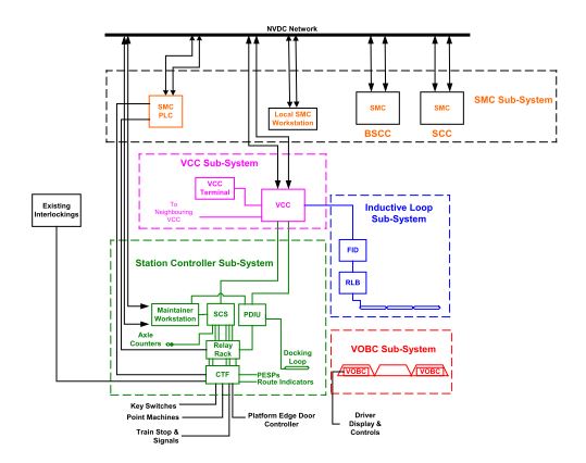
* SELTRAC Overview
* SCS Electronics Rack Overview
* SCS/Relay Rack Interface
* ACE/Relay Rack Interface
* Reference Documents
SELTRAC OVERVIEW
SCS ELECTRONICS RACK OVERVIEW
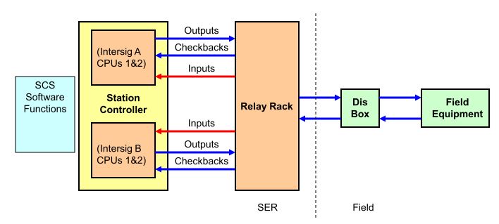
* Each SCS contains two computers known as ‘INTERSIG A’ and ‘INTERSIG B’.
* INTERSIGS are duplicated for availability – either INTERSIG A or B can be in control, but not both.
* INTERSIG switchover is automatic if one fails.
* Every relay controlled by an INTERSIG output is checked to ensure it is in the commanded position (energised or de-energised) – if not, the INTERSIG shuts down and switches over.
* Each INTERSIG runs the same software, and the I/O allocation for both INTERSIGs must be the same!.
SCS OUTPUTS
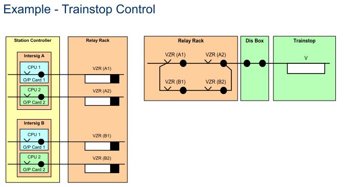
* For vital output functions, both CPUs of the controlling INTERSIG are required to energise separate outputs.
* These outputs are combined on the relay rack, and must be in correspondence to give a permissive output to the field (e.g. to lower a trainstop)
* All output circuits energise BR930 series relays.
* There are two types of SCS output cards : Solid State output cards (1-5) and Force Actuated Relay (FAR) Cards (1-4).
* Solid state output cards use transistor switching, and require the load relays to be fitted with diodes for back EMF suppression.
* FAR output cards contain relays for switching the output loads on and off, and do not require diodes on the load relays.
* Point control outputs can only be allocated to certain outputs.
* Output circuit power is 50V DC supplied from the relay rack busbar.
Each output card is controlled by one of the two CPUs.
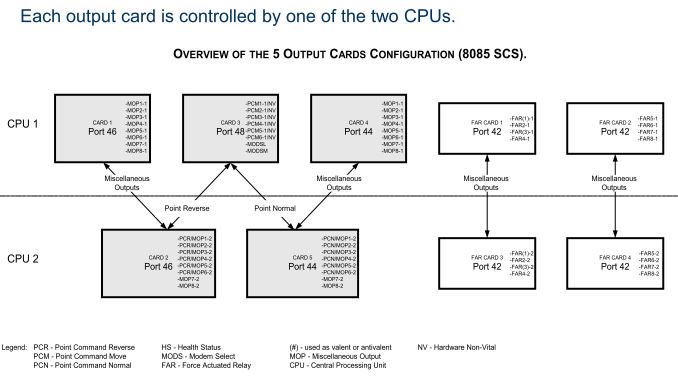
* For vital functions, one output is required from both CPUs.
* For this reason output cards are paired together to give two outputs.
* For all outputs (except point move outputs):
* Solid state output cards 1 & 2 and 4 & 5 are paired together i.e. the functions on cards 1 & 2 are the same and the functions on cards 4 & 5 are the same.
* FAR cards 1 & 3 and 2 & 4 are also paired together.
* For point move outputs, a combination of outputs from solid state cards 2 & 3 or 3 & 5 is required (refer to relay rack presentation for more details about points).
•Each output relay is individually checked-back to it’s controlling INTERSIG via back contacts (NOTE: point control relays are checked back differently).
•These check-back inputs prove that the relays have operated correctly.
•The check-back input is on when the output is off and off when the output is on!
•If the check-back input does not correspond with the output state, the INTERSIG halts and switches over to the other one.
•The other INTERSIG uses a completely different set of output relays, so it can continue to operate.
•An alarm is raised if the INTERSIG switches over because of failure.
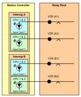
Status Input Example – PESP Inputs – NB only one plunger shown for clarity
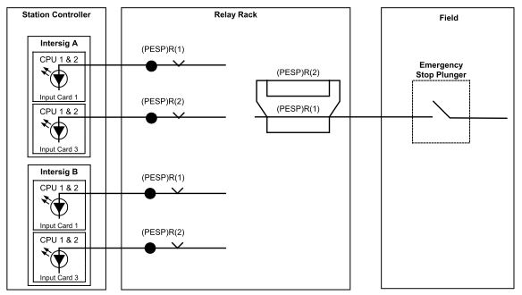
•Two types of input: checkback and status
•Each output relay is individually checked-back to it’s controlling INTERSIG via back contacts (points are checked back differently)
•All status input circuits use separate contacts for each input –controlling 2 inputs off one contact is not permitted.
•Each input is read by both CPUs, but vital inputs must be input to two separate input cards, using contacts of two separate relays.
•There are four input cards in each INTERSIG: 1 paired with 3 and 2 paired with 4.
•Point detection inputs can only be allocated to certain inputs
•SCS input circuits are powered from a 24V DC supply within the SCS, which is looped around the relay contacts on the relay rack
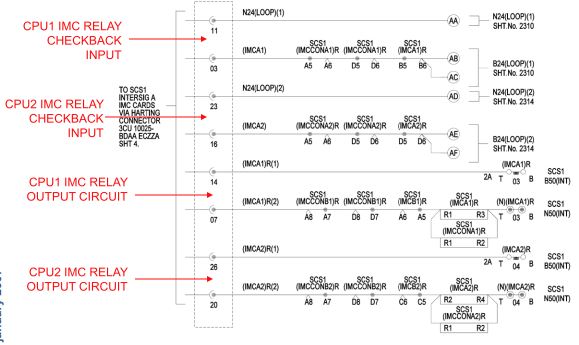
•The two CPUs of each controlling INTERSIG provide IMC (Interval Measuring Circuit) outputs to the relay rack, which are energised when the INTERSIG is functioning normally and it is the controlling INTERSIG.
•If a CPU detects a fault, its IMC outputs are de-energised.
•Each IMC output energises a pair of relays on the relay rack – one contactor relay (with high current front contacts) and one standard relay.
•There are checkback inputs for the IMC relays. These inputs are on the IMC card in the INTERSIG – NOT to an input card.
Example – IMC output and checkback circuits for INTERSIG A.
Each INTERSIG has a secure busbar controlled by the IMC contactor relay (example for INTERSIG A shown below).
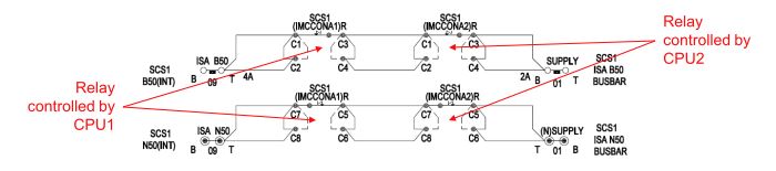
* When the INTERSIG’s two CPUs are both healthy and in control, the secure busbar is energised.
* The secure bus (ISA B50/N50) is used to power all of INTERSIG A’s output relays.
* INTERSIG B has a separate secure bus (ISB B50/N50) controlled by its IMC contactor relays.
* If the INTERSIG is faulty or not in control, the secure bus is de-energised and all the output relays will be too!
* INTERSIG A and B use separate modems to communicate with the VCC
* The relay rack is responsible for enabling the transmission path of the correct modems and for selecting the correct modems.
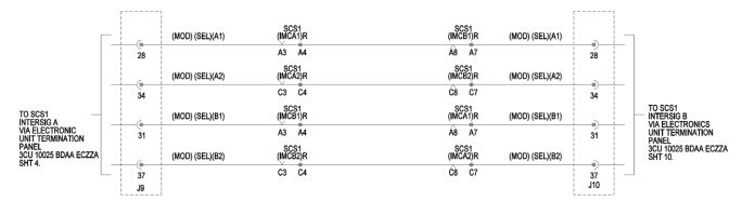
MODEM CONTROL
* These circuits enable the correct modem transmission path. (TXEA)R and (TXEB)R are energised directly from the INTERSIG A and B secure bus respectively.
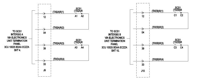
This circuit uses the standard (non-contactor) IMC relays to select either the INTERSIG A or B pair of modems to be the ones that transmit to the VCC.
•Every night, when no trains are running, the SCS does a self-test.
•As part of this test, it switches off it’s IMC outputs.
•This causes the IMC relays to drop, which causes the secure bus to be switched off.
•The SCS monitors its checkback inputs to ensure that all its IMC relays respond to the test (i.e. the back contacts make). If they do, the SCS re-energises the IMC outputs again and returns to normal operation.
•If the test is failed (because the IMC relays have failed), then an alarm is raised.
•On JNUP, there are many inputs associated with Emergency Stop Devices (ESDs). These inputs (and relays) are energised 99.9% of the time (e.g. PESPs, Track Circuit Interrupters etc.)
•These input relays could fail so that they are stuck in the ‘up’ position on these circuits, and nobody would know until the ESD was operated.
•On JNUP we power all ESD relays with their own secure busbar.
•NOTE: This is a separate secure busbar from the one that powers the INTERSIG output relays.
ESD SECURE BUS
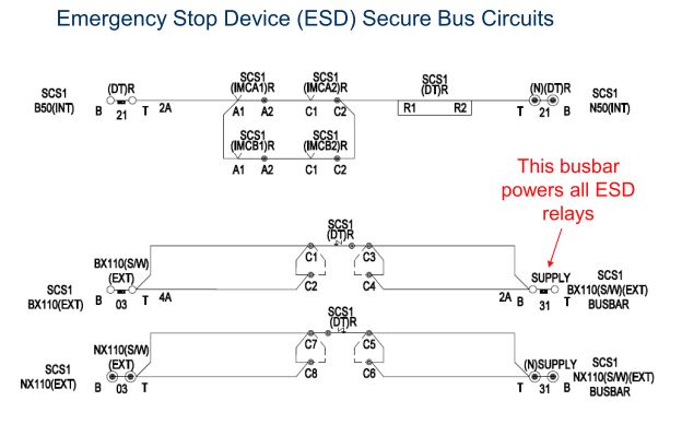
•During the nightly IMC test, the IMC relays are switched off. This causes the (DT)R relay to be switched off too.
•The (DT)R relay causes the ESD busbar (called ‘BX110(S/W)(EXT)’) to be de-energised.
•All ESD relay circuits (PESP, TCI etc.) are powered from the BX110(S/W)(EXT) busbar, and so these circuits are also switched off during the IMC test.
•The SCS checks that the ESD relay inputs are de-energised. If they are, all the ESD relays have operated correctly and the test is passed.
•If an input does not respond correctly to the test, an alarm is raised.
ACE Interface
• Each SCS cabinet contains an Axle Counter Evaluator (ACE) which calculates if there is a train in each axle counter block connected to it.
• The occupied/clear status of each axle counter block is passed to the VCC through the modem link.
• Most axle counter blocks do not need a relay on the relay rack.
• However, for some functions, normally for deadlocking points, the ACE provides a relay output to the relay rack.
• The ACE has its own health relays (similar to the INTERSIG’s IMC relays), its own secure bus for its relay outputs and its own special checkback circuit.
• The ACE has two CPUs, similar to the INTERSIG. But, unlike the INTERSIG, the ACE is not duplicated (there is only one ACE per SCS).
•When the ACE is healthy, it energises two contactor relays on the relay
rack, called TKUE1 and TKUE2.
•If the ACE is faulty, one or both of these is de-energised.
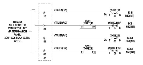
The TKUE relays are used to control an ACE secure bus.
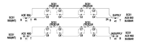
All ACE output relays are powered from the ACE B50/N50 busbar, so that if the ACE is faulty, all the ACE output relays are de-energised
and all the axle counter sections appear occupied to the relay rack.
ACE Outputs – Example for axle counter block ‘AC(1)’
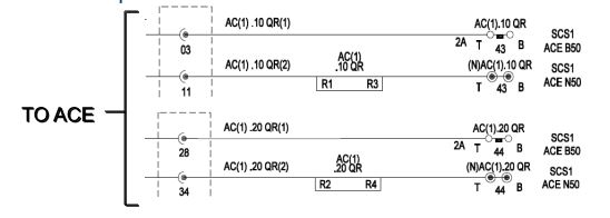
For each axle counter block, the ACE energises two relays, .10 QR and .20 QR, both of which must be in correspondence to prove that the block is clear.
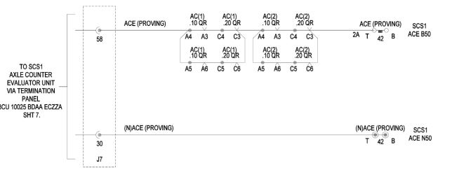
•ACE relay checkback circuits for blocks AC(1) and AC(2). Note this is a combined checkback circuit for EVERY RELAY controlled
by this ACE.
•Relays are not checked back individually to the ACE.•This ‘supervision input’ is checked every night by the ACE self-test.
All ACE output relays are powered from the ACE B50/N50 busbar, so that if the ACE is faulty, all the ACE output relays are de-energised
and all the axle counter sections appear occupied to the relay rack.
* During the ACE self test, firstly TKUE1 relay is de-energised.
* This switches off the ACE B50/N50 busbar, all the ACE output relays and the ACE checkback input.The ACE checks that the checkback input is off and then re-energises the TKUE1 relay. The ACE checks that the checkback input is on again.
* The test is repeated by de-energising the TKUE2 relay.
Summary
* Each SCS has two INTERSIGs, either of which can be in control but not both
* Two relays are proved in correspondence for each vital SCS input or output.
* All output relays are checked back to the INTERSIG to proved they have operated correctly
* The IMC outputs are used to provide a secure bus, which switches off the INTERSIG’s outputs if it detects a fault
* The IMC outputs are used to enable modem transmission to the VCC
* Emergency stop device relays are powered from a secure bus
* ACE outputs are powered from a secure bus and are checked back to the ACE
Useful Documents
* Relay Rack Hardware Requirements Specification – 3CU 00550 0210 DTZZA
* SCS Electronics Rack Wiring Schematic – 3CU 10025 BDAA ECZZA
* INTERSIG Parallel Input/Output Interfaces – 3CU 00550 0198 PBZZA
* Station Controller Subsystem Requirements Specification –3CU 00550 0051 DTZZA