Return paths for Traction current and suppression at source
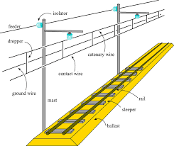
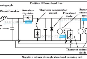
1. Current is collected from the OLE by the train pantograph and taken to the train equipment
2. Having passed through equipment on train, current passes through axles and wheels of the traction unit to the running rails.
3. Current is returned to the feeder Station either by traction return running rails which are connected to Feeder station with cables or by return conductors
4. Part of current is returned to the Feeder station through the general mass of earth
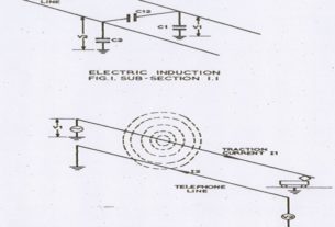
5. Decision on whether to use rail return or return conductors has historically been determined by susceptibility of nearby Telecom cables to inductive interference
Rail return
- Simplest return path provided for traction current is “rail return”
- One rail of each track is normally designated as “traction return rail”. On plain track it is normally rail nearest the cess.
- In areas of complex arrangements traction return rail changes in order to meet track circuit arrangements but by cross bonding a continuous path must be maintained throughout
Return conductors
- Additional conductor that carries traction return current in antiphase to current in catenary and the net electromagnetic effect on lineside telecommunication cables is reduced.
Reduction is of order of 45%
- RCs provide alternative path for return traction current and percentage of current flowing in these is dependent upon impedance of this path compared with return rail/earth path impedance
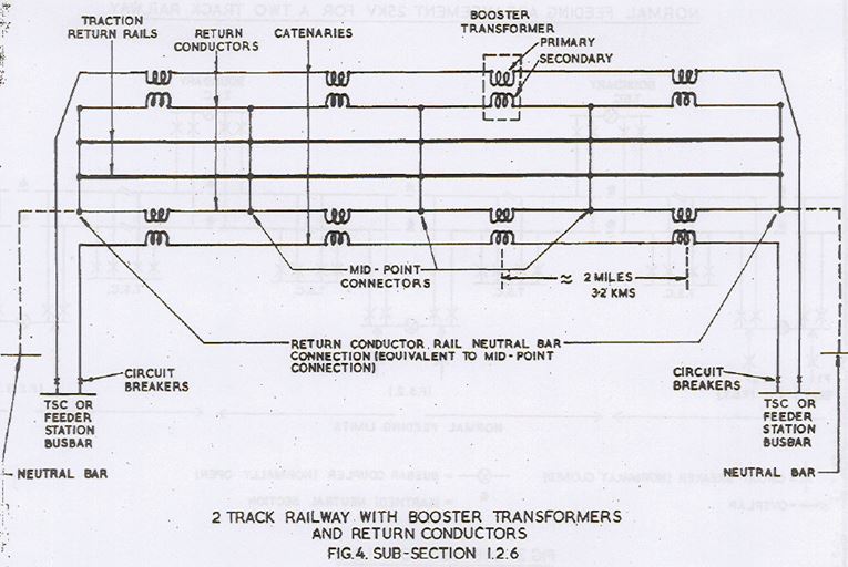
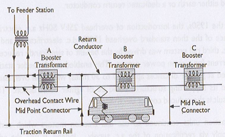
Booster Transformers/return conductor (BT/RC) system
To improve matters further current must be forced or driven through RCs and ideally 100% of return current is required in the RCs. This is achieved through Booster Transformers
Booster transformers are installed at overhead line overlap spans generally at intervals of 3.2 Kms
Primary winding is connected in series with 25 KV overhead line conductor system and secondary wining in series with associated return conductor
Return conductors are supported from the overhead line structures by insulators and are connected to the running rails midway between BT locations, and to the neutral of the incoming 25 KV supply at the feeder stations (bonds are called mid point connectors).
Effect of BT
– Produce current in RC which approximates catenary current in magnitude but is in antiphase (opposite direction of flow in secondary winding)
– Secondary circuit of BT is low impedance loop via RC, adjacent mid point connectors and rail/earth
Each BT deals with a 2 mile section
Maximum suppression of induction is achieved with a traction load located at a mid point connector, and the minimum suppression when traction load is at a BT
With load at mid –point connector, BT/RC system can reduce induction by as much as 95%
Booster Transformer