Railway Points and Track circuits
Railway Points and Track circuits:- Points
- Normal lie points
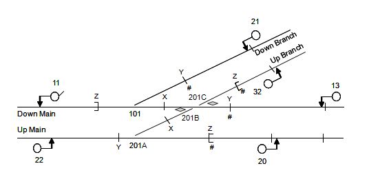
- Points Numbering
- Overlap
- Replacement Joint
- Berth track circuit
- Point Zone
- TC Numbering
Railway Points and Track circuits – Normal lie of points
Selection Criteria
- the most obvious is that whereas the straight route through a set of points can be safely traversed at a high speed, the diverging route inevitably consists of a quite sharp radius curve.
- where a point provides trapping protection, in order to protect the running line from an unauthorised movement by a train or individual errant vehicles from a siding or depot.
The safety benefit in each case is given by the interlocking arrangements which ensure that the relevant point is designed to be placed (and, in general, locked) in the safest position. It is conventional to define this safest position as the “Normal” lie, but it is important to realise that the safety benefit does not automatically arise from the nomenclature alone; rather it indicates an intention to impose the relevant locking. The normal position of points numbered as a crossover shall give parallel movements.
Elsewhere, where reasonably practicable, the normal position of points shall:
- lead a movement onto a line used predominantly in the same direction as the movement or into a siding;
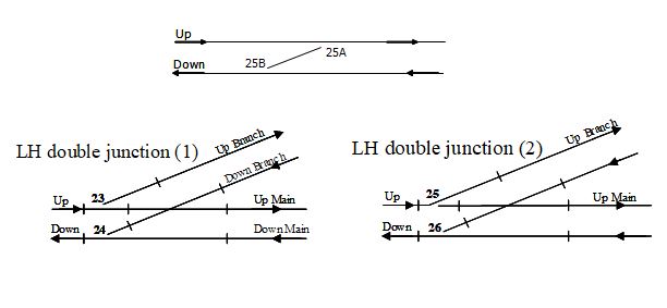
- be arranged to reduce conflicts, for example at double junctions;
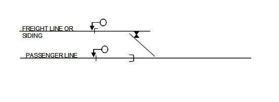
- derail vehicles at trap points;
- when the above does not apply, be the straight or main route through the points.
Siding points

Numbering
Point Identity
Worked points, the train operated points and unworked points that are detected in the signalling system shall have an identity that is unique to the controlling signal box. Points with two or more ends that are required to be operated together shall be identified by a common identity and a unique suffix for each end.
Each signal box shall have a convention for the allocation of suffixes. Where practicable, the suffixes for new layouts shall increment alphabetically in the down direction. It is permissible to follow established conventions where existing layouts are modified.
Unworked points in running lines that are not detected in the signalling system shall have an identity in a distinct sequence, similar to that for worked points.
Railway Points and Track circuits
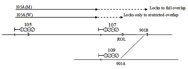
Overlaps
- Standard Overlap – 180 metres
- But Suggested Overlap (Robust train protection) – 225 metres
- Try to avoid points and level crossings within the overlap to avoid
- Complex controls Operational restriction
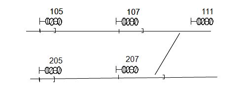
Alternate Overlaps

205 à 207 requires points 301A/B Normal or Reverse
Warning Class
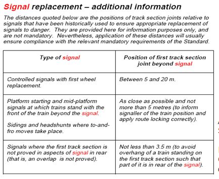
Replacement Joint
Berth Track
Wherever practicable berth track shall be designed such that it can accommodate the longest train
- To ensure the train is standing at a signal
- To release the route cleared by the train
- To allow Platform sharing
Other Factors
- for purposes of approach release of the signal.
- to initiate the activation of a level crossing sequence for an automatic crossing, or turn on the picture / commence auto-lowering of CCTV / MCB crossings,
- to enable the signaller to be given adequate information for operational purposes regarding the whereabouts of trains, for example:
where there is the use of a platform by multiple trains for example the provision of separate track indications can be helpful when operating the layout,
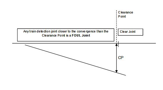
Fouling point and Clearance Point

Point Zone
Track circuit Interrupter
Switch Diamond Crossing
Maximum / Minimum Lengths
The maximum length is essentially determined by the actual technology but is influenced by the environment; track circuits need to operate reliably and are sensitive to ballast resistance.
The minimum length is essentially determined by the rolling stock permitted to use the line. It is undesirable to have any portion of a track section that is shorter than the maximum distance between the inner axles of a vehicle since the track could show clear when it has no axles on it yet is being spanned by a vehicle. i.e.18.3m
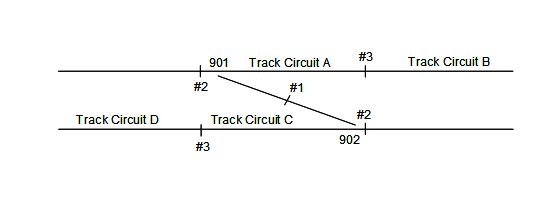
Numbering
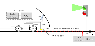
Train detection
Track section identity
Each track section (track circuit or axle counter section) shall be allocated a defined identity. The identity shall be unique to the signal box or locality. Regardless of signal box or locality code prefixes, there shall be sufficient separation between track sections with similar identities to avoid confusion. When two or more track sections give a common indication at the signal box, each track section shall be identified by the identity of the signal box indication and a unique suffix.
Train detection
Equipment identity
Train detection equipment associated with track sections shall be identified by the track section identity and where necessary suitable suffixes.Train detection equipment not associated with track sections shall be identified in a distinct alphabetic sequence separate from track sections (eg treadle A, treadle B, etc.)
Jointless track circuits
Track circuit ppt
DC track circuit
Track circuit PDF
DC track circuit diagram
Track circuit bonding
DC track circuit consists of
Railway track circuit Diagrams