Railway Point Detection Circuits
‘V’ Style Frame Chairlock Point Circuits
The Point Control, Lever Lock and Indication circuits for Chairlocks are identical to the Four Foot point circuits already discussed.
Detection
Unlike Four Foot points, a Chairlock layout uses two separate and independent detection units, one for each rail switch. Each unit proves that its corresponding switch is either fully home and locked or open sufficiently.
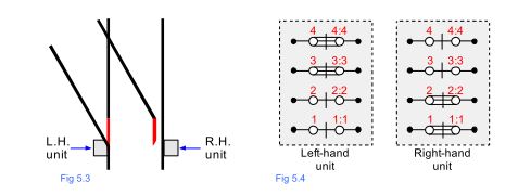
The four contacts in each unit are labelled four, three, two and one with the number four contact always drawn at the top as shown in the contact arrangements for both layouts Figs 5.2 and 5.4.
If the right-hand switch is closed when the points are Normal (Fig 5.1) this will be a Normal contact. It follows that the left-hand unit is the opposite (Fig 5.2).
Right hand unit
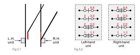
If the right-hand switch is open when the points are Normal (Fig 5.3) it will be a Reverse contact. It follows that the left-hand unit is the opposite (Fig 5.4).
left hand unit
Although there are four contacts in each unit, contact number one is used exclusively for the control of the WL and therefore there are only three contacts available for the detection circuit. Number two contact is used for the open switch detection and contact numbers three and four are used for the closed switch detection.
The detection circuit needs to check the contacts in both units before picking up the WKR. If the left-hand turnout above is in the Normal position (Fig 5.3) the right-hand unit proves that its associated switch is open a minimum of 3 1/2″ (89 mm). The left-hand unit proves that its switch is both fully home and locked.
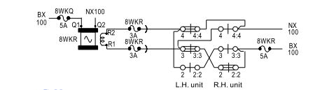
Fig 5.5 below shows a typical detection circuit for a left hand turnout, single ended set of Chairlocks. The BX supply to the WKR is always fed to the right-hand unit on terminal 3:3 (this is also the same for a right-hand turnout) from here it is looped to 2:2 on the same unit. The feed then goes to 3:3 on the left hand unit to the WKR. The NX returns via 4 and 4:4 on the left hand unit.
As with Four Foots the looping in the units is there to change swap the BX and NX supplies over in order to drive the three position WKR Normal or Reverse.
Left-hand turnout, single ended Chairlock detection circuit
It should be noted that there is no WL proving contact in the circuit as it is indirectly proved via the mechanical design of the Chairlock unit. The contact box is sprung to the neutral position and relies on the WL to maintain pressure on the cam follower arm which in turn follows the profiles of the lock and switch detection cams to make the contacts.
If the WL is not fully de-energised it will not apply pressure on the cam follower arm and therefore the contacts will remain broken (regardless of whether the points are actually mechanically home and locked).
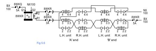
Fig 5.6 below is an example of a left hand turnout, double ended layout detection circuit.